8
INSTALLATION-SYSTEM PIPING
If you are installing an entire new heating
system, rst install all of your radiation units
(panels, radiators or cabinets) and the Supply
and Return Mains - then make the connections
at the boiler.
In connecting the cold water supply to the water
valve, make sure that a clean water supply is
available. When the water supply is from a well
or pump, a sand strainer should be installed at
the pump.
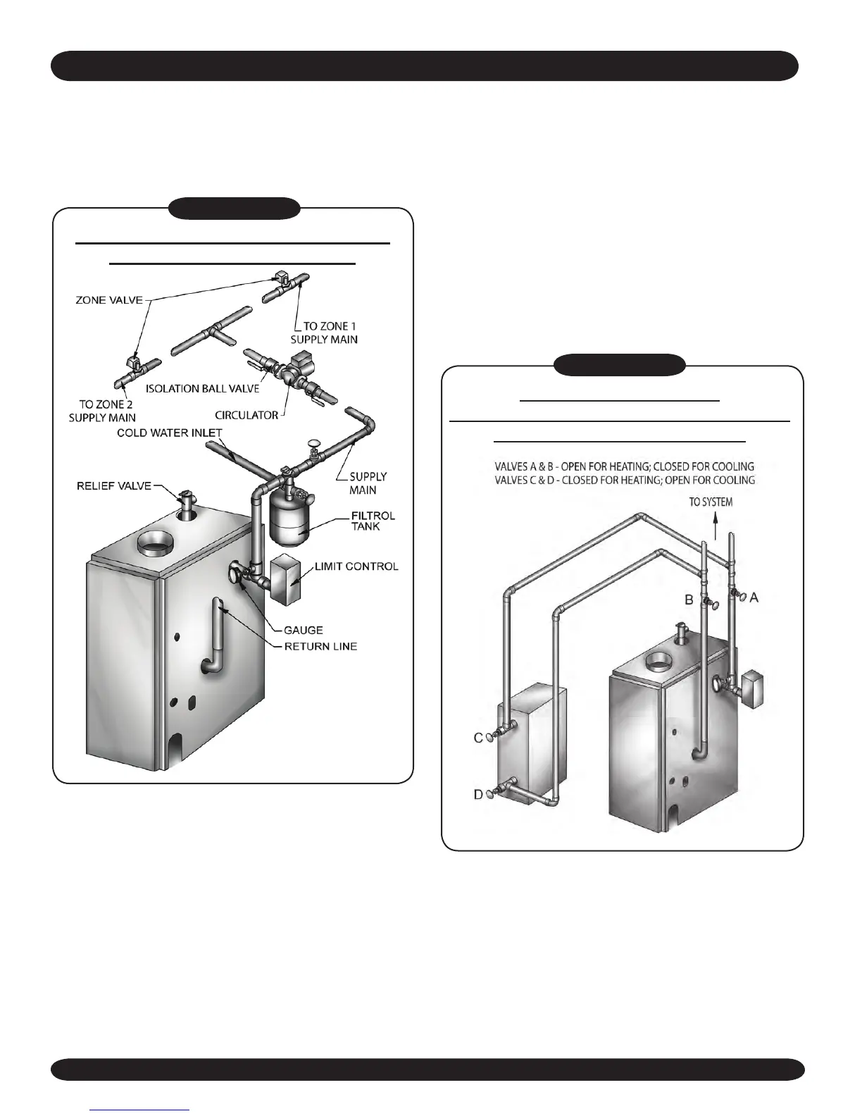
Figure #5
FORCED HOT WATER TYPICAL PIPING
WITH ZONE CONTROL VALVE
A hot water boiler installed above radiation level
must be equipped with a low water cutoff device.
A periodic inspection is necessary, as is ushing
of oat type devices, per manufacturers specic
instructions.
Figure #6
PIPING ARRANGEMENTS
FOR BOILER WHEN USED IN CONNECTION
WITH REFRIGERATION SYSTEM
When the boiler is used in connection with
refrigeration systems it shall be installed so that
the chilled medium is piped in parallel with the
heating boiler with appropriate valves to prevent
the chilled medium from entering the heating
boiler (Figure #6).
If the boiler is connected to heating coils located
in air handling units where they may be exposed
to refrigerated air circulation, the piping system
shall be equipped with ow control valves or other
automatic means to prevent gravity circulation of
the boiler water during the cooling cycle.
5. Connect Supply and Return Lines to boiler.
The connections may require certain
additional ttings and parts, as shown in the
diagrams in Figures #4 and #5.