7
FRESH AIR DUCT CAPACITIES (1 Square inch per 3,000 Btuh)
Fresh Air
Duct Size
100% Free Area
1/4” Wire Mesh
75% Free Area
Metal Louvers
25% Free Area
Wood Louvers
3” x 12” 108,000 81,000 27,000
8” x 8” 192,000 144,000 48,000
8” x 12” 288,000 216,000 72,000
8 ½” x 16” 384,000 288,000 96,000
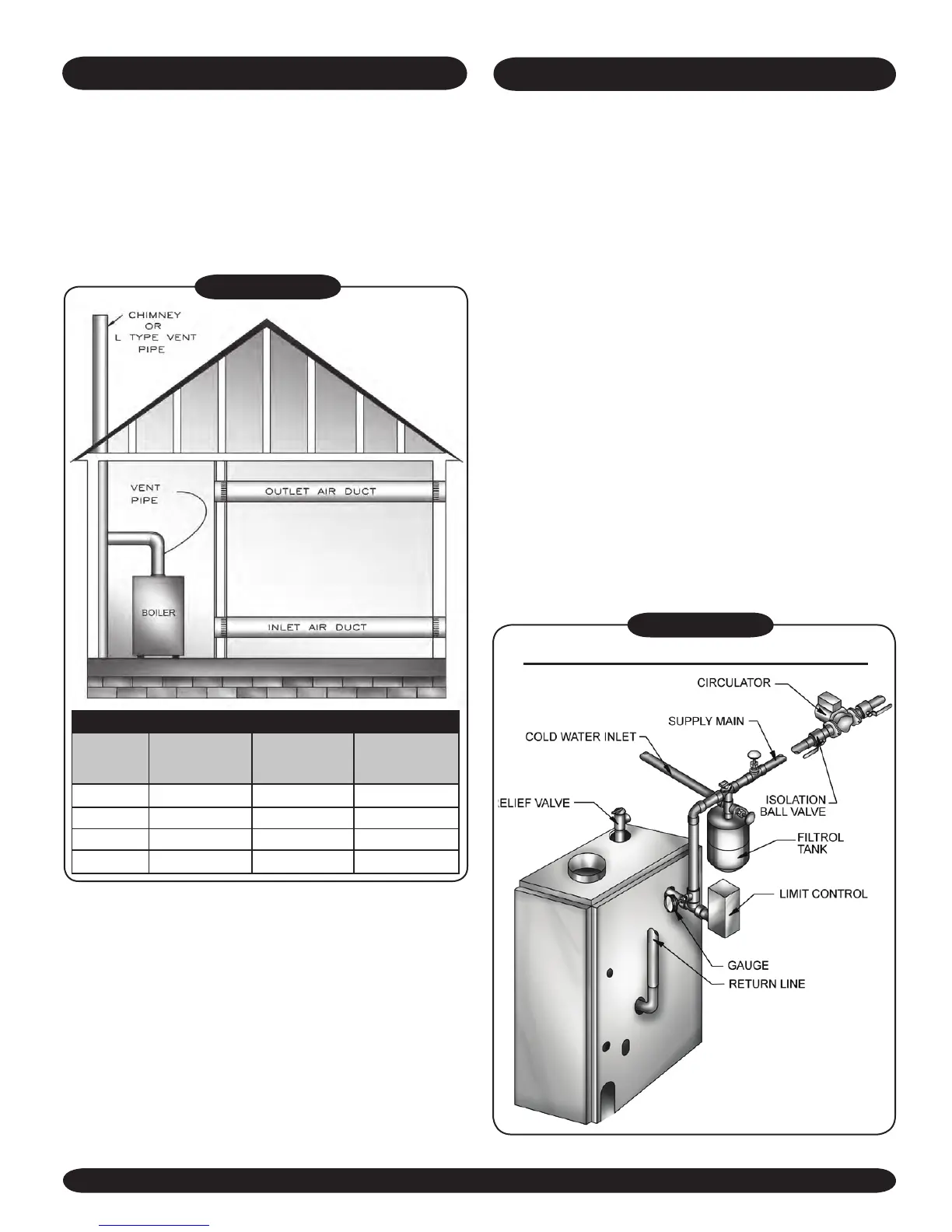
Figure #3D
FRESH AIR FOR COMBUSTION
a) 1 sq. inch per 3000 Btu per hour of the
total input of all equipment located in the
enclosure, and the front of the appliance
(see Figure #3D).
b) Not less than the sum of the areas of all vent
connectors in the conned space.
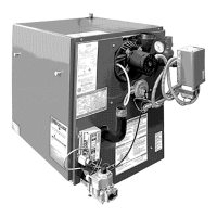
INSTALLATION-SYSTEM PIPING
1. Place boiler in the selected location (as near
chimney as possible). Your boiler is shipped
assembled. You need only to install the circulator,
ball valves the relief valve with a drain line to carry
any water to a drain, and the drain valve.
2. Install Relief Valve on 3/4”pipe nipple in tapped
opening in the left end section. Connect a
drain line of the same pipe size (3/4” to carry
any water away to a drain. No shutoff of any
description shall be placed between the safety
relief valve and the boiler, or on discharge pipes
between such safety valves and the atmosphere.
Installation of the safety relief valve shall conform
to the requirements of the ANSI/ ASME Boiler and
Pressure Vessel Code, Section IV.
3. Install Drain Valve on lower left side of boiler
as marked.
4. Install Temperature and Pressure Gauge into ¼”
bushing threaded in tee furnished with supply
piping (see Figures #4 and #5)
FORCED HOT WATER TYPICAL PIPING
Figure #4