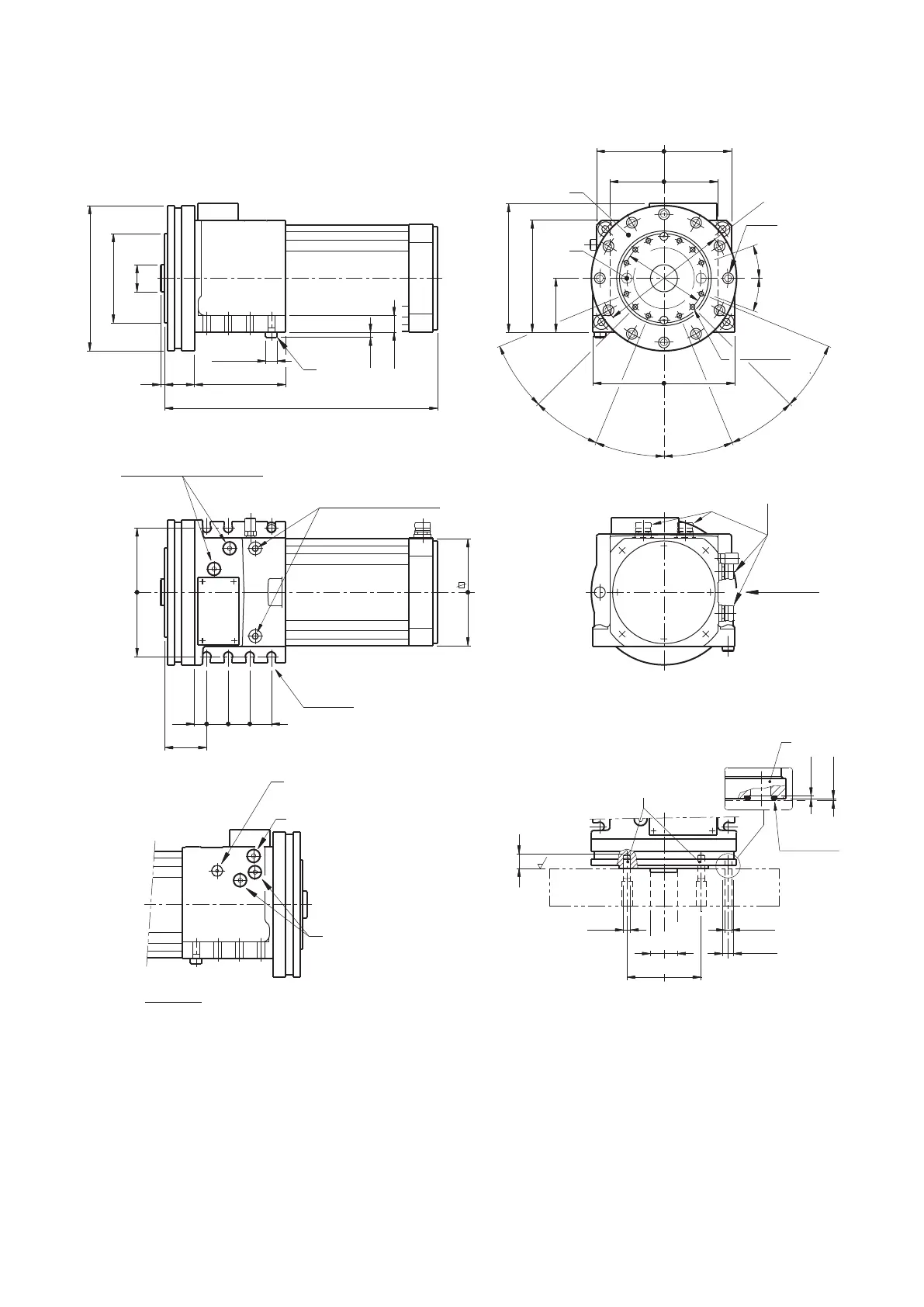
1) Inlet coolant position.
2) Coolant outlet position.
3) Adjustable coolant ring.
4) Coolant outlet displacement range.
5) Positions for boring the disc reference pins.
6) Reference pin.
7) Hydraulic connections.
8) Electrical connectors.
Note: E1 version, connectors on the top.
9) Safety valve.
10) Reference pins between tool disc and turret.
11) Note: Main overall dimensions and xing interchan-geables
with SM
*
turrets
(6)
(4)
(3)
(2)
(5)
=
190
160
=
M8x15
166
25
190,5
7,5
210
120
158
400
135
Ø 132
Ø 40
40
6
Ø 215
N°2 M10 (for lifting)
32
32
for M10
190
18
58
32
BACK VIEW
+0,1
0
80
20°
20°
==
==
==
(7)
A - B 1/4" GAS
CONNECTORS
(8)
200
==
"A" view
Ø17
g6
"A" view
R - 1/4" GAS
(1)
(9)
0
– 0,005
(3)
ø10
ø40
ø110
ø16
ø10
22 max
0,8
1,4
~ 0,2
OR 2050
TOOL DISC INTERFACE
+ 0,003
– 0,005
(7)
A1 - B1 1/4" GAS
(Additional ports)
(10)
22°5
22°5
22°5
22°5
22°5
22°5
3.4-DM-16/10Overalldimensions
3.4.a-DM-16/10Rightversion


 To Next Page