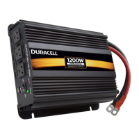
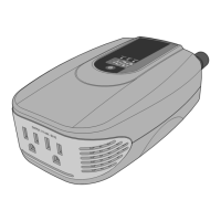
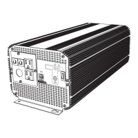
1000/2000/3000 Watt High Power Inverters
User Guide
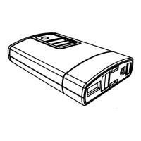
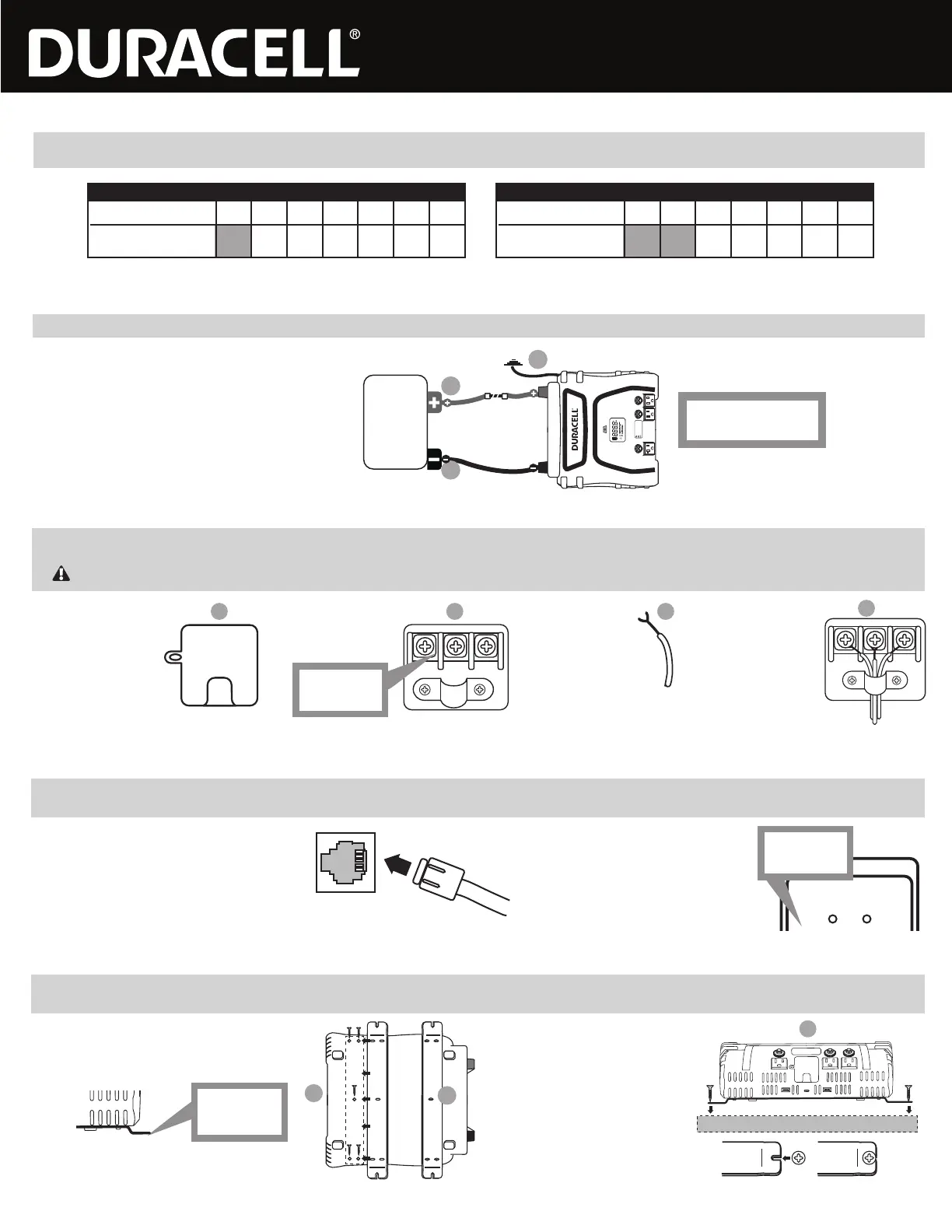
The remote On/Off switch is included with the 3000 Watt inverter and is also an option (sold separately) for the 2000 Watt inverter. This switch enables you to conveniently activate/deactivate the inverter without having to be
right next to the unit itself. The remote switch features an 8-foot cord, enabling you to place this switch within easy reach.
Remote On/Off Switch (2000 Watt / 3000 Watt Inverters)
A. Connecting the remote switch: Plug the modular
cable into the connector on the back side of the inverter
located below the power input terminals.
B. Using the remote switch: In order to use the
remote, the inverter On/Off switch must initially be
in the OFF position (all LED lights on the inverter
are dark). The inverter can then be turned ON or
OFF with the remote switch.
LED (Green) - INVERTER ON
LED (Red) - INVERTER FAULT
INVERTER REMOTE
CONTROL ON / OFF SWITCH
POWER FAULT
LEDs are off
when switch
is OFF
Your 3000 Watt inverter can also be wired directly to any AC outlet, device or appliance inside your TV, trailer or work vehicle to provide battery power on an ongoing/permanent basis. This is ideal for items that you wish to
access power directly from your source battery without having to plug the intended outlet/appliance into the inverter’s AC outlets every time. The inverter allows one direct-wired connection via this AC terminal.
A. Locate the 110V AC
output terminal (see
Product Features) on
the front panel of your
inverter.
B. Use a Phillips head
screwdriver to
remove the cover and
access the terminals.
C. Expose no more than
½” of conductor from
each wire.
D. Thread the wires
through the strain relief.
Loosen the screw on
each terminal; place the
exposed wire end
around the screw
threads (behind the
screw head) and then
re-tighten the screw to
secure the connection.
Direct-Connect AC Terminal (3000 Watt Inverter)
IMPORTANT: AC extension wire and socket are not included with this inverter. Each wire should be no thicker than 10AWG.
A B C
D
AC 110V OUTPUT
L N GN
AC wire colors:
Line/Hot – Black or Brown
Neutral – White or Blue
Ground – Green or Green/Yellow
L N GN
L= Line/Hot
N = Neutral
GN = Ground
See diagram below. Install a UL-listed fuse in-line with the red input cable, as close to the battery as possible. Ensure tight connections.
A. Connect the negative (black) terminal
of inverter to the negative battery post.
Permanent Connection
(2000 Watt / 3000 Watt Inverters)
POS
NEG
FUSE
Battery
IMPORTANT: To avoid accidental battery discharge
disconnect the inverter when not in use. USB ports
will remain active when the inverter is turned off.
OPERATION: Press the power button for two seconds
to turn the inverter on and off.
FAULT MODE: Press and release the power button
to silence alarm. To manually reset the inverter
turn it off and back on.
-
+
C
B
A
B. Connect the positive (red) terminal
of inverter to the positive battery post.
C. Connect the ground terminal according to the
GROUNDING section above.
Fuse size
2000 Watt Inverter: ANL-200
3000 Watt Inverter: ANL-300
If you choose to use a power cable other than the included 6AWG power cables, use the thickest gauge and shortest length allowed by your configuration and budget. As a rule of thumb no more
than 2% loss should be allowed. The chart below lists minimum specifications; please consult a wire gauge chart for longer installations.
Power Cable Selection
(2000 Watt / 3000 Watt Inverters)
2000W (100A)
Wire Gauge (AWG) 8 6 4 2 1/0 2/0 4/0
Maximum Cable Length
(2% voltage drop) N/A 2.9 4.6 7.2 11.5 14.5 23
3000W (250A)
Wire Gauge (AWG) 8 6 4 2 1/0 2/0 4/0
Maximum Cable Length
(2% voltage drop) N/A N/A 1.8 2.8 4.6 5.8 9.2
You may mount your inverter for permanent installation using the included mounting brackets. These brackets allow you to conveniently attach your inverter to a wall, under a cabinet, inside a closet or other location inside
your RV, trailer or work vehicle.
Mounting Brackets (2000 Watt / 3000 Watt Inverters)
A. Line up the mounting brackets: Turn the inverter
over and locate the mounting holes on the bottom
panel. Ensure that the mounting brackets are in the
proper position as shown below:
B. Attach the brackets to the inverter: Use
the included screws to securely fasten the
brackets to the bottom panel.
C. Mount the inverter: Use your own screws
to securely fasten the inverter to the
mounting surface (wall, counter, cabinet,
etc). Fit the screws into the slots at each
end of the mounting brackets before
tightening.
A
B
C
AC 110V OUTPUT
Align the mounting slots on the bracket with the
mounting holes on the inverter.
Bends should
face downward/
away from inverter
Mounting Surface
 Loading...