16
open levers to separate the lower inner cover and the lower cover.
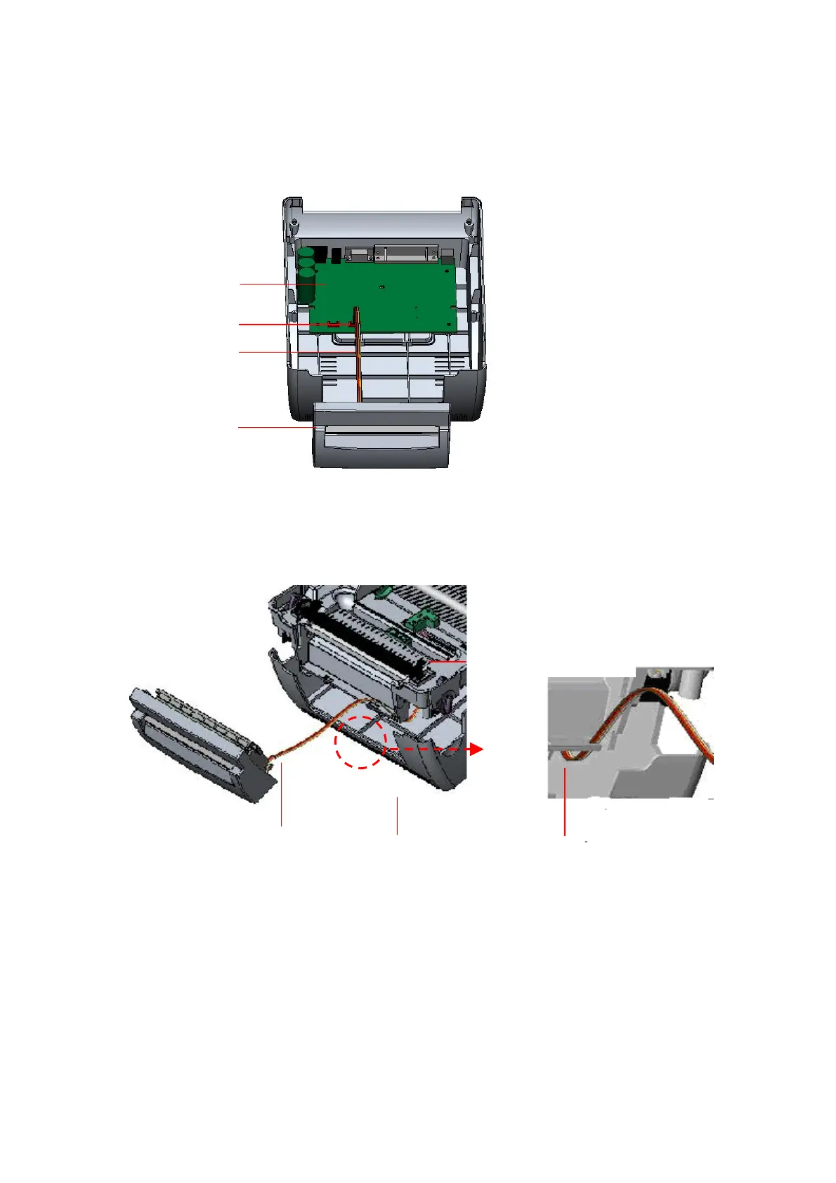
7. Arrange the cable through the bezel. Connect the cutter module cable to the 4-pin
socket on printer PCB.
Fig. 24 Cutter module installation
Fig. 25 Cutter module cable arrangement
8. Arrange the lower inner cover back to the lower cover.
9. Install the cutter into the niches of the printer.
PCB
4-pin Socket
Cutter Cable
Cutter
Lower Inner Cover
Lower CoverCutter Cable
Bezel