9
ASSEMBLY
UNPACKING
• This product has been shipped completely assembled.
• Carefully remove the tool and any accessories from the box. Make sure
that all items listed in the packing list are included.
• Inspect the tool carefully to make sure no breakage or damage occurred
during shipping.
• Do not discard the packing material until you have carefully inspected and
satisfactorily operated the tool.
WARNING: If any parts are missing do not operate this tool
until the missing parts are replaced. Failure to do so could
result in possible serious personal injury.
WARNING: Do not attempt to modify this tool or create
accessories not recommended for use with this tool. Any
such alteration or modifi cation is misuse and could result in
a hazardous condition leading to possible serious personal
injury.
WARNING: To prevent accidental starting that could cause
serious personal injury, always put in locked position when
assembling parts.
OPERATION
APPLICATIONS
You may use this tool for the following purposes:
• Drilling* • Driving screws
• Driving cup hooks • As a socket driver
* Drill bits not included
WARNING: Do not allow familiarity with tools to make you
careless. Remember that a careless fraction of a second is
suffi cient to infl ict serious injury.
WARNING: Always wear safety goggles or safety glasses
with side shields when operating tools. Failure to do so
could result in objects being thrown into your eyes, result-
ing in possible serious injury.
WARNING: Do not use any attachments or accessories not
recommended by the manufacturer of this tool. The use of
attachments or accessories not recommended can result in
serious personal injury.
WARNING: Battery tools are always in operating condition.
Therefore, switch should always be locked when not in use
or carrying at your side.
SWITCH TRIGGER
To turn the tool ON, depress the switch trigger. To turn it OFF, release the
switch trigger.
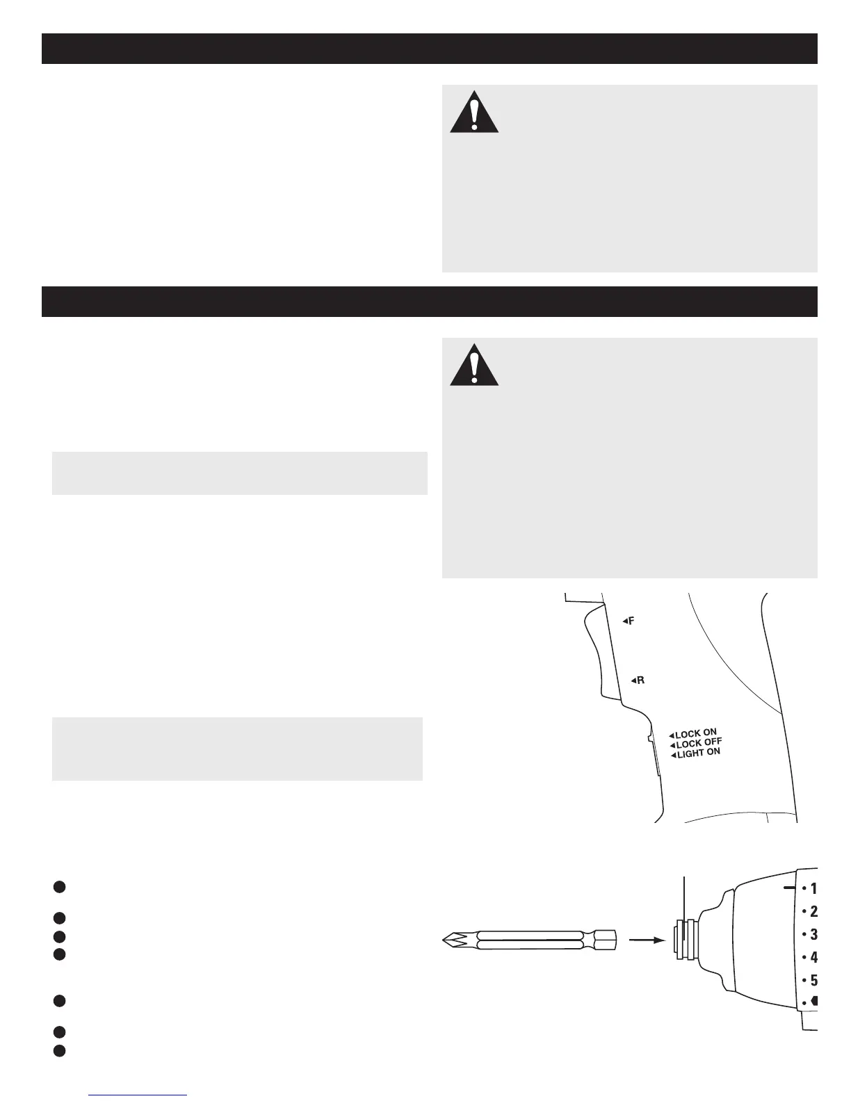
SWITCH LOCK
The switch trigger can be locked in the OFF (top) position. This feature can
be used to prevent the possibility of accidental starting when not in use.
To lock switch trigger, place the switch in the top position. Slide switch to
center for normal operation, slide to bottom to activate LED light.
REVERSIBLE
This tool has the feature of being reversible. The direction of rotation is
controlled by a switch. Push the top of the switch for forward (clockwise),
push the bottom for reverse (counter-clockwise).
BUILT-IN CHUCK
The tool has a built-in chuck. The chuck has been designed
to accept 1/4 in. hex bits.
INSTALLING BITS
Lock switch trigger on the tool by placing the direction
of rotation selector in top position.
Slide the chuck forward and hold in position.
Insert bit straight into chuck.
Slide the chuck back slowly and release.
REMOVING BITS
Lock switch trigger or the drill by placing the direction
of rotation selector in top position.
Slide the chuck forward and hold in position.
Pull bit straight out of chuck.
CAUTION: The metal surface may become hot during use. Avoid
contact with it to avoid possible burn injury.
CAUTION: To prevent gear damage, always allow chuck to come
to a complete stop before changing the direction of rotation. To stop,
release switch trigger and allow the chuck to come to a complete stop.
1
2
3
4
1
2
3
SLIDE FORWARD
SWITCH TRIGGER
SWITCH LOCK