5
• If the difference between the required temperature and that of the iron tip is greater
than 10° “WAIT” displays on the LCD.
• To change from °C to °F press
o
C /
o
F button. The display shows °C or °F after
the temperature gure.
• When the desoldering tip reaches the desired temperature place over the solder
connection on the back of the PCB.
• When the solder melts, pull the trigger on the desoldering iron.
• The solder will be collected in the reservoir on the top of the iron.
• If the tip becomes blocked use the correct size cleaning wires (supplied) to clear
the blockage.
Removing solder waste:
The reservoir must be emptied of solder waste regularly or the efciency of operation
will be impaired.
• Switch off the mains power and allow the desoldering gun to cool.
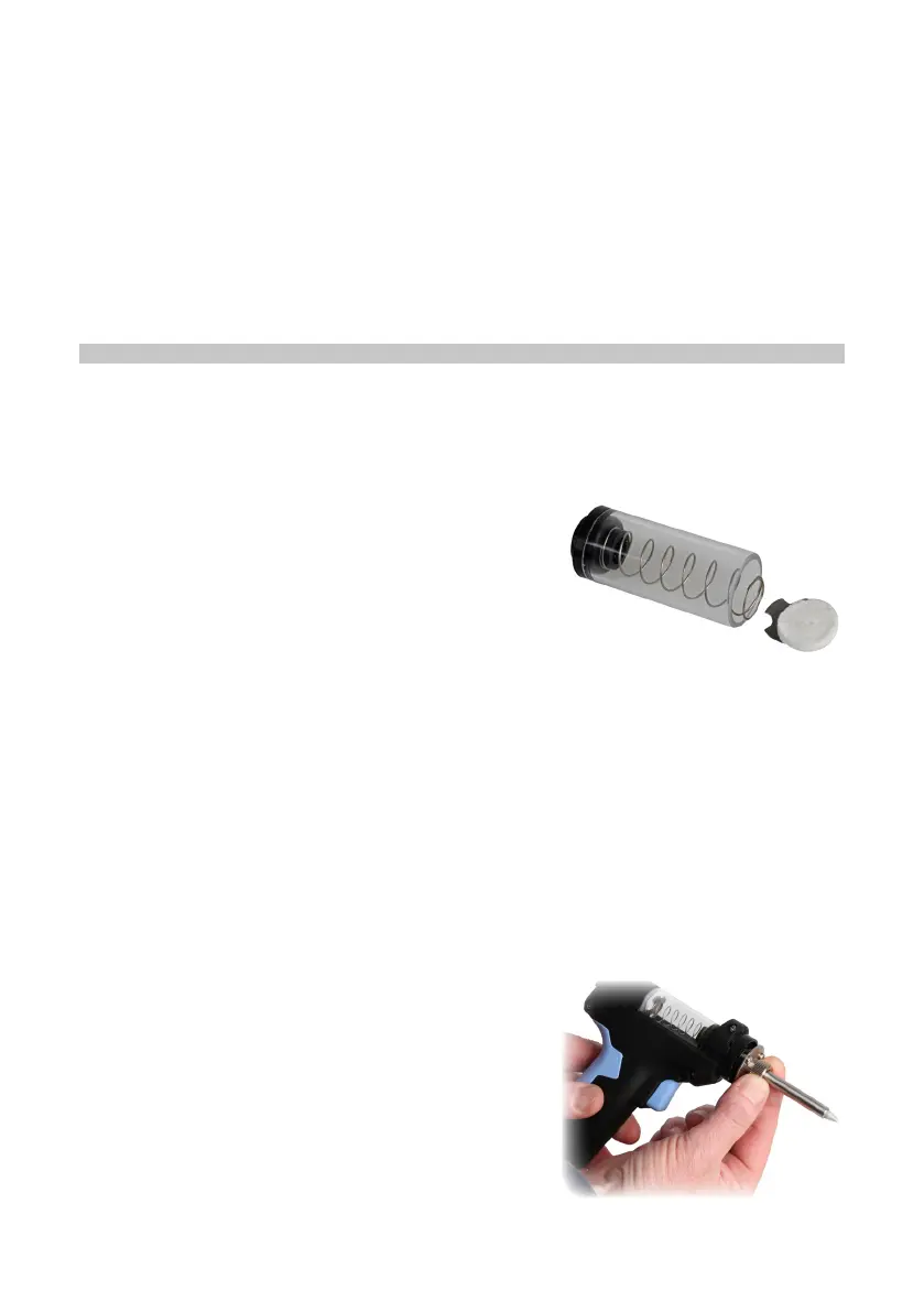
• Slide the rear cover clear from the reservoir.
• Lift out the reservoir while retaining the lter pad
and spring plate in position.
• Remove the lter pad and spring plate and empty
out the waste from the reservoir.
• Replace the spring plate and lter into the rear end of the tube and re-insert into
the gun ensuring the spring plate and lter are fully engaged inside the tube and
the front end is slotted into the gun fully.
• Press on the end of the rear cover and slide it back into position.
NOTE: a new lter pad can be tted during this process if the one in use is becoming
dirty or worn.
MAINTENANCE
Replacing the desoldering tips:
• There are 3 different diameter tips supplied with this iron.
• Replacing the tip should only be done when the iron is switched off, unplugged
and allowed to cool.
Caution: Damage could occur if the iron is left powered on without the tip tted.
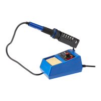
• Unscrew the knurled nut and remove the outer
tube retainer.
• Invert the tube and the tip will drop out.
• After removing the tip, blow out any oxide dust
that may have formed in the tip retaining area of
the iron.
Caution: Care should be taken to avoid getting dust in your eyes.