8
RMO40TD Description
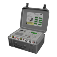
5.2 Mains power and ground connectors
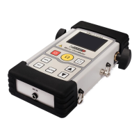
Motor Current connector
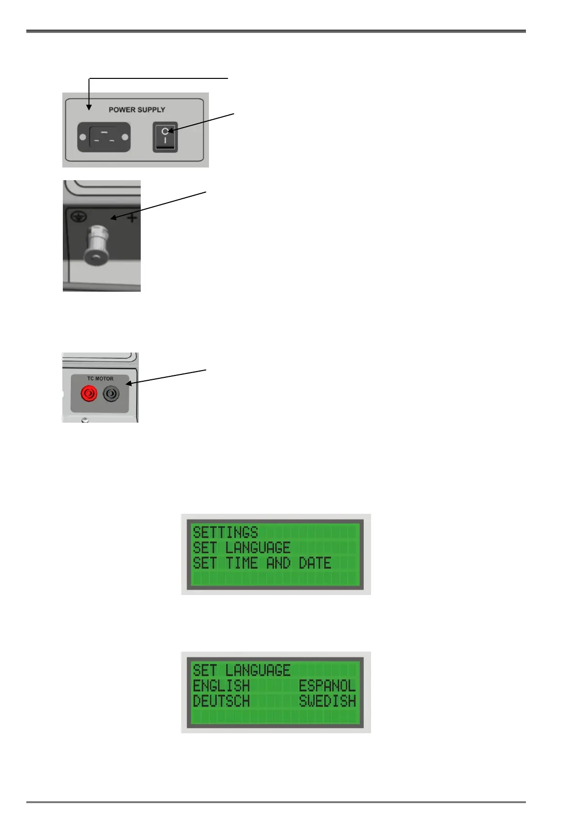
5.3 Settings
To set RMO40TD time and date press START at the same time with SET, to select the
Settings menu.
Setting RMO40TD’s Language
To set RMO40TDRIGHT, and then ENTER to select the Set Language menu.
Move the cursor to the bottom line using LEFT/RIGHT, and select the language with ENTER.
Pressing ENTER to confirm, returns you to the Main menu.
Pressing STOP to cancel, returns you to the Main menu.
Connector for mains power supply
Power switch
I In this position, RMO40TD is connected to the
mains power supply.
0 In this position, RMO40TD is separated from
the mains power supply with both poles.
Earth/ground connector.
For protection against parasitic currents or voltages, always connect
RMO40TD earth/ground connector to protective ground (PE). Use
only the original cable.
For safety reasons, always establish this connection as the first
one before you do any other connections, and separate this
connection as the very last one.
Figure 5-2:
The Language
menu
Figure 5-1:
The Settings menu
AC current monitoring channel is intended for monitoring and
recording the OLTC mechanical-drive motor-current during tap
changer operation. The motor current waveform is also printed on the
DV Win generated graph, and can help in detecting OLTC mechanical
problems. An AC current clamp is available for purchase.
 Loading...