G2030-II-S
Apr ‘19
- 25
Variable Speed Drive (cont’d)
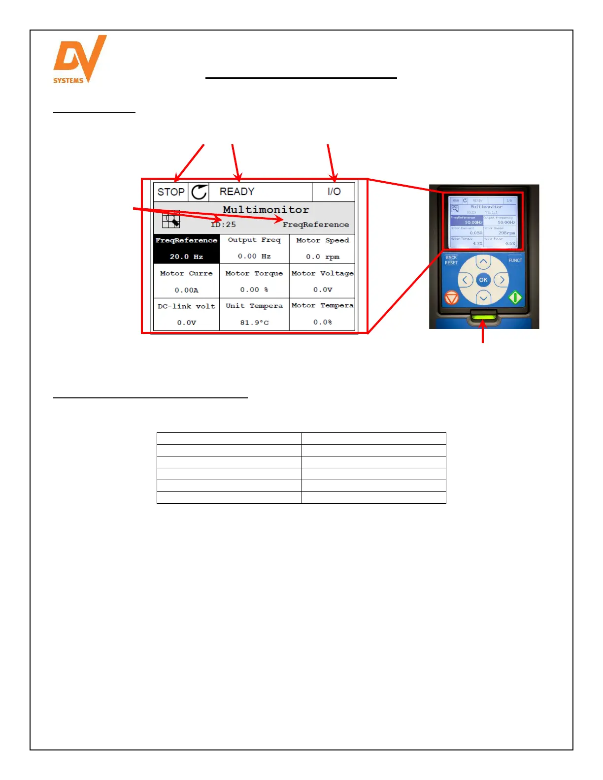
Operating Screen
Typical Drive Status Indicators on Screen
The Status LED of the drive shows the status of the drive. It can show 5 different statuses.
Blinking slowly Ready
Green Run
Red Fault
Orange Alarm
Blinking fast Downloading software
The status of the drive is also indicated on its graphical display.
Status Fields: STOP / RUN and READY / NOT READY / FAULT
Control Place: PC / IO / KEYPAD / FIELDBUS. The default Control Place shall be ‘I/O’.
Location Field: the parameter ID number and the current location in the manual.
Default page of the graphical display is set to Multimonitor. On this Multimonitor page, 9 drive status items are
displayed.
Output Frequency: The output frequency to the motor
Frequency Reference: The frequency reference to motor control. It varies between min. and max. frequency.
Analogue Input 2: The input speed signal as a percentage of the used range.
Motor Current: The measured current at the motor leads
DC Link Voltage: The measured voltage at the drive capacitors.
Motor Speed: The actual speed of the motor.
Unit Temperature: The heatsink temperature of the VFD.
Motor Temperature: The calculated motor temperature in percentage of the nominal working temperature.
Slot A DIN 1, 2, 3: The status of the digital input 1~ 3.
 Loading...