G2030-II-C
Mar ‘17
- 19 -
Variable Speed Drive (cont’d)
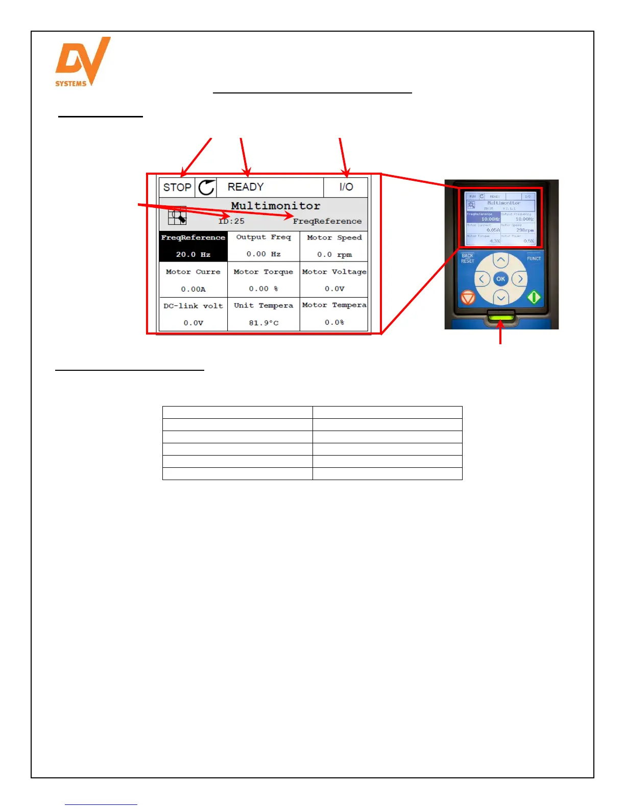
Operating Screen
Typical Drive Status Indicators
The Status LED of the drive shows the status of the drive. It can show 5 different statuses.
Color of the LED light Status of the drive
Blinking slowly Ready
Green Run
Red Fault
Orange Alarm
Blinking fast Downloading software
The status of the drive is also indicated on its graphical display.
Status Fields: STOP / RUN and READY / NOT READY / FAULT
Control Place: PC / IO / KEYPAD / FIELDBUS. The default Control Place shall be ‘I/O’.
Location Field: the parameter ID number and the current location in the manual.
Default page of the graphical display is set to Multimonitor. On this Multimonitor page, 9 drive status items are
displayed.
Output Frequency: The output frequency to the motor
Frequency Reference: The frequency reference to motor control. It varies between min. and max. frequency.
Analogue Input 2: The input speed signal as a percentage of the used range.
Motor Current: The measured current at the motor leads
DC Link Voltage: The measured voltage at the drive capacitors.
Motor Speed: The actual speed of the motor.
Unit Temperature: The heatsink temperature of the VFD.
Motor Temperature: The calculated motor temperature in percentage of the nominal working temperature.
Slot A DIN 1, 2, 3: The status of the digital input 1~ 3.
Status Fields Control Place
Location Field
Status LED