INSTALLATION
1. LOCATION: Select a location where the temperature of
the unit will be between 20°F and 120°F. Distance from
the receiver is limited only by total loop resistance. See
“Electrical Connections”. The tubing feeding pressure
to the instrument can be run practically any length
required but long lengths will increase response time
slightly. Avoid surfaces with excessive vibration.
2. POSITION: All standard models are calibrated with the
diaphragm vertical and should be used in that position
for maximum accuracy. If your application requires
mounting in other than a vertical position, be sure to
specify this when ordering.
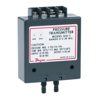
3. PRESSURE CONNECTIONS: For convenience, two
sets of 1/8˝ female NPT ports are available. Plug the
unused set with pipe plugs provided. Attach tubing
from positive pressure source to port marked “HI” or
from negative (Vacuum) source to port marked “LOW”.
In either case, opposite port must be vented to atmos-
phere. In dusty environments, we recommend use of an
A-331 Filter Vent Plug to keep interior of instrument
clean. For differential pressures the higher source is
connected to the “HI” port and lower to the ”LOW” port.
4. MOUNTING: The Series 605 Transmitter may be either
panel mounted or surface mounted.
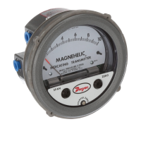
A. PANEL MOUNTING: Cut a 4-3/4˝ or 120 mm dia.
hole in panel and insert the complete unit from the
front. Slip on the mounting ring and install the split
snap ring in the groove on the bezel. Seat the mount-
ing ring against the snap ring and thread the four
screws through the tapped holes. Tighten screws
against rear of panel.
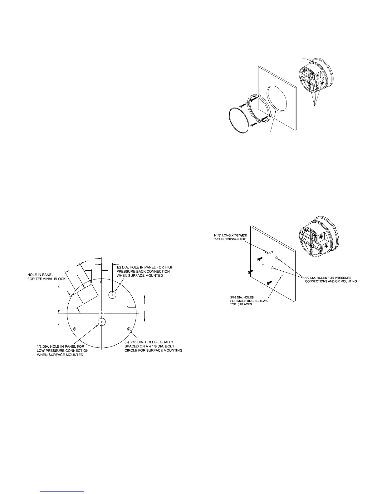
B. SURFACE MOUNTING: Drill (3) 3/16˝ dia. holes for
mounting screws and cut (1) 7/8˝ x 1-1/8˝ hole for
access to terminal strip as shown in hole location
drawing. Insert screws from rear of panel and thread
into tapped holes on back of transmitter case. If rear
pressure connections are to be used, make 1/2˝ dia.
holes located as shown in hole location drawing in left
column.
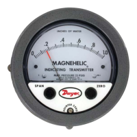
5. ZEROING: Once gage/transmitter is mounted in its
final position, check to be sure pointer aligns with zero
on scale, when no pressure is applied and both low and
high pressure ports are vented to atmosphere. To
adjust, turn small slotted screw at center-bottom of
gage face. Do not move the larger black knobs labeled
SPAN and ZERO. These are for use only if a calibration
check shows the 4-20 mA output signal to need adjust-
ment. See page 3 under heading OUTPUT RANGING.
7
17/32
1-7/8
7/8
1-1/8
30°
11/16
21/32
1-3/4
SNAP RING GROOVE
PNEUMATIC PRESSURE TAPS
4-3/4 DIA. HOLE
E-68 8/2/07 8:43 AM Page 2