DWYER INSTRUMENTS, INC.
Phone: 219/879-8000www.dwyer-inst.com
P.O. BOX 373 • MICHIGAN CITY, IN 46361, U.S.A. Fax: 219/872-9057 e-mail: info@dwyer-inst.com
©Copyright 2007 Dwyer Instruments, Inc. Printed in U.S.A. 8/07 FR# 01-440559-00 Rev. 3
5. Relieve all pressure, allow a few seconds for setting
and adjust the ZERO knob for a 4 mA current loop
reading.
6. The SPAN and ZERO controls are slightly interactive so
steps 4 & 5 should be repeated a few times until read-
ings of 4 and 20 mA are obtained consistently.
7. Remove the milliammeter from the current loop and
proceed with final installation of the transmitter and
receiver.
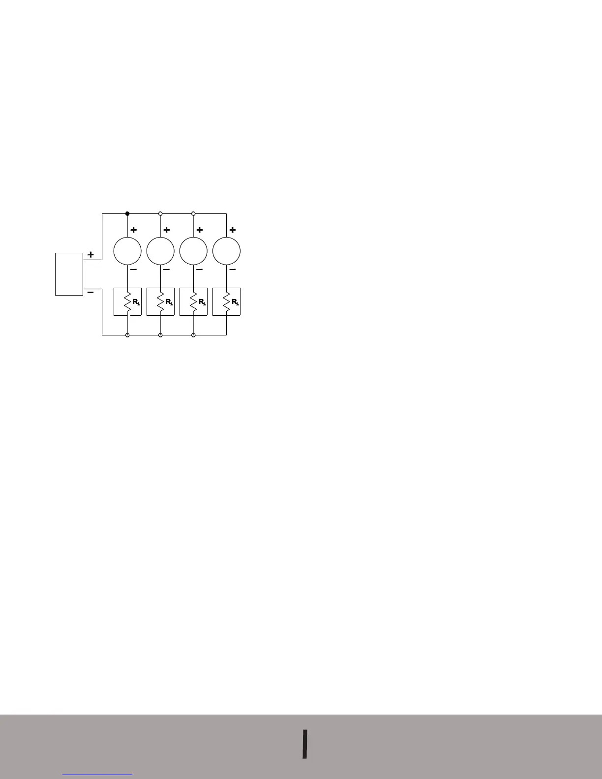
POWER
SUPPLY
10.0-35
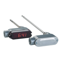
SERIES
605
SERIES
605
SERIES
605
SERIES
605
Several Series 605 transmitters can be operated with a sin-
gle power supply as depicted above in Figure D. Be care-
ful to specify a supply with sufficient capacity. The minimum
current requirement at a given voltage can be calculated by
multiplying the number of units x 20 mA. In the example
shown this would be 4 x 20 or 80 mA minimum.
MAINTENANCE
Upon final installation of the Series 605 Transmitter and the
companion receiver, including the A-701 Digital Readout,
no routine maintenance is required. A periodic check of
system calibration is recommended. The Series 605
Differential Pressure Transmitter is is not field repairable and
should be returned, freight prepaid, to the factory if repair is
needed (field repair should not be attempted and may void
warranty). Be sure to include a brief description of the prob-
lem plus any relevant application notes. Contact customer
service to receive a return goods authorization (RGA) num-
ber before shipping.
Figure D
MULTIPLE UNITS WITH COMMON POWER SUPPLY
E-68 8/2/07 8:43 AM Page 4