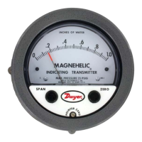
MOUNTING
Panel Mount:
Provide a 4-9/16˝ diameter opening in panel. Insert gage and secure in place with
provided screws and mounting lugs.
Surface Mount:
Provide three 3/16˝ diameter holes in panel on a 4-1/8˝ diameter bolt circle. Cut an
opening for the terminal block as shown in Figure 2.
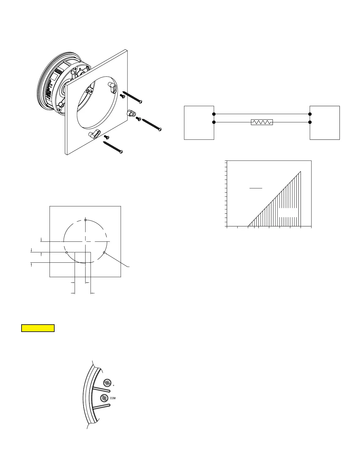
ELECTRICAL CONNECTIONS
Electrical connections are made to the terminal block located in the back of the
transmitter. Terminals are marked + and COM (see Figure 3 below).
Wire Length
The maximum wire length connecting the transmitter to the receiver depends on the
on the wire gage and the resistance of the receiver. When calculating loop resistance,
wiring should not contribute more than 10% of the receiver resistance. For runs over
1000´, choose a receiver with greater resistance. When wiring length is less than 100´,
22 AWG wire can be used.
2-Wire Operation
An external power supply delivering 10-35 VDC with minimum current capability of
40 mA DC (per transmitter) must be used to power the control loop. See Figure 4 for
connection of the power supply, transmitter, and receiver. The range of appropriate
receiver load resistance (RL) for the DC power supply voltage available is expressed
by the formula and graph in Figure 5. Shielded two wire cable is recommended for
control loop wiring. If grounding is required, use the negative side of the control loop
after the receiver.
SELECT UNIT OF MEASUREMENT
To select a unit of measurement, press and release the UNITS button to cycle through
the available options. The LCD will display the current selected unit.
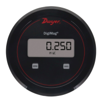
Figure 1: Panel mount
Figure 4
Figure 5
Figure 2: Surface mount
Figure 3
[3] HOLES FOR #6 SCRE
EQUALLY SPACED ON
4-1/8 [104.78] B.C.
1 [25.40]
1 [25.40]
Do not exceed specied supply voltage ratings, as doing so will
result in permanent damage not covered by warranty. This unit is
not designed for 120 or 240 V AC line operation.
CAUTION
1400
1300
1200
1100
1000
900
800
700
600
500
400
300
200
100
50
Total Receiver Resistance Ω
Maximum Value (1250)
R Max. =
0 5 10 13 15 20 25 30 35 40
L
Vps–10.0
20mA DC
Operating
Region
SERIES DM
PRESSURE
TRANSMITTER
-
+
RECEIVER
POWER
SUPPLY
10-35 VDC
-
+
+-
 Loading...