Rev. 10/98 7 949-1239-3
936
+
-
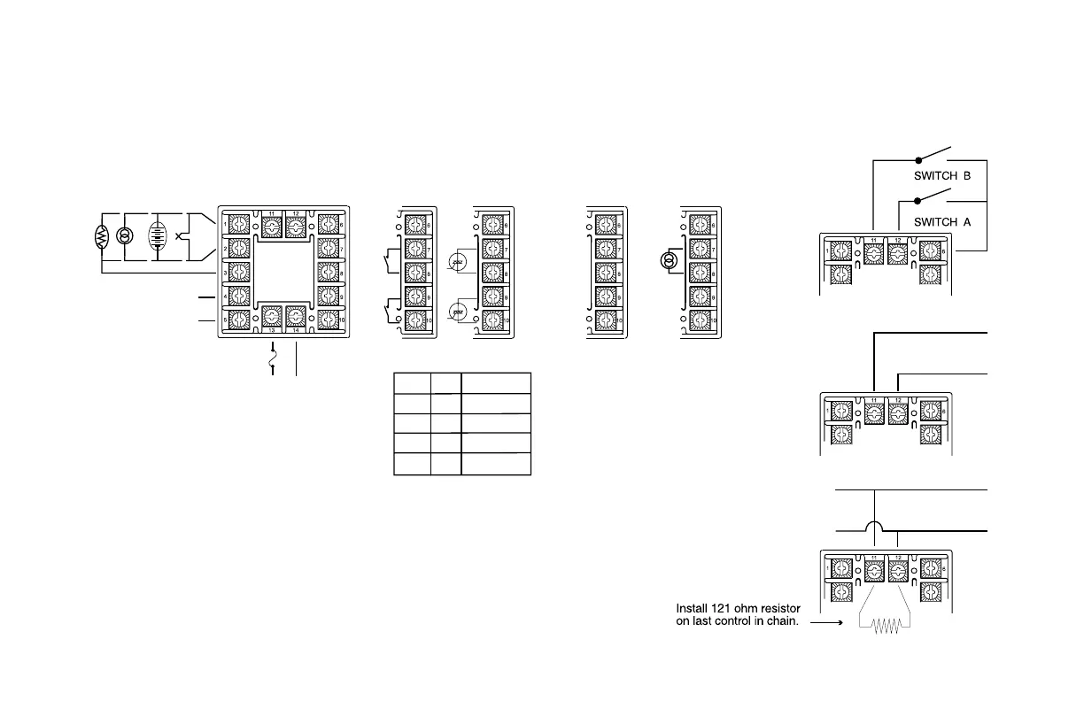
B (+)
A (-)
992
RTD*
Current
Voltage
Therm
ocouple
+
-
* For 2-wire 1000 Ω RTD use terminals 1 & 3.
For 2-wire 100 Ω RTD use terminals 1 & 3, and
place a jumper wire between terminals 3 & 4.
F1
3/8 A @250 VAC
Medium Lag
INPUTS
Line Input See Rating
Label for details
AL1
ALARM OUTPUT
Terminals 4 & 5 are
Normally Open. See
Rating Label.
+
-
F1
}{
Relay**
N.O.
Solid State Relay
N.O.
5VDC Output
5V = On, 0V = Off
5VDC @
25mA
-
+
Current or
Voltage
+
-
}{
5VDC @
25mA
-
+
+
-
0 to 10 VDC @ 25 mA
}{
}{
Output
A
Output
B
˚C ˚F CURRENT
25 77 3.50
35 95 2.75
45 113 2.00
55 131 1.25
SSR Derating Chart
For Relay or SSR
outputs use type MDA or
3AB 3.5A medium lag
fuse.
** R/C snubber is
recommended for driving
solenoid or contactor
loads.
INPUT WIRING: Do not run thermocouple of other signal wiring in the same conduit as power
leads. Use only the type of thermocouple or RTD probe for which the instrument has been
programmed. See Secure Menu for Input Programming.
For thermocouple input always use extension leads of the same type designated for your
thermocouple.
Outputs A and B may be logically swiched. See Secure Menu for details.
948
OPTIONS
WIRING
 Loading...