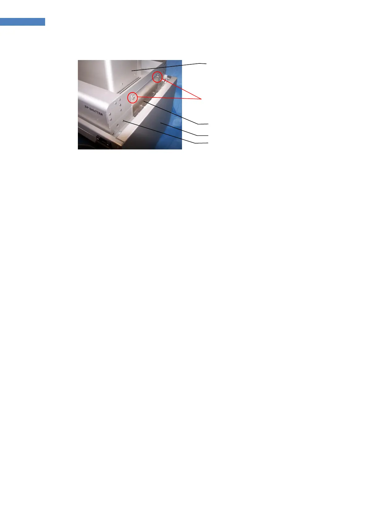
Figure 10. Component Mounting Order
8. Center the Shutter on the Light Shield. When the desired position is achieved, tighten the
Securing Brackets to the Light Shield.
9. Once the system components are properly mounted, connect the system cables and cords (Figure
11):
a. Interconnect Cable, PN 40695 – Connect one end of the cable to the J3 Receptacle on
the Reflector Housing and the opposite end to the Lamp Power Receptacle on rear panel
of the Power Supply.
b. Interconnect Cable, PN 40879 – Connect one end of the cable to the J4 Receptacle on
the Reflector Housing and the opposite end to J1 Receptacle on the ECE ZIP Shutter.
c. Interconnect Cable, PN 40878 – Connect one end of the cable to the J5 Receptacle on
the Reflector Housing and the opposite end to the receptacle on the rear of the ECE
Light Shield.
d. If the foot switch is used, connect it to the Foot Switch Jack (J2) on the ECE ZIP Shutter.
e. Plug the Power Cord into the Power Module located in the rear panel of the Power
Supply (Figure 12). Plug the opposite end into an external AC source. Turn on the Main
Power Switch.