I
I
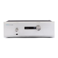
This
completes
the
assembly
of
your
Dynatuner.
You
should
now
make
one
final
inspection
of
the
unit
to see
that
all
connections
are
soldered.
One
poor
solder
connec-
tion
can
upset
the
performance
of
your
tuner,
or
prevent
proper
aHgmnent.
Be
sure
that
there
are
no
loose wire
clippings.or
pieces of solder,
and
that
there
are
no
bridges
of
solder
across
insulated
areas
of
the
circuit
boards.
Check
to
be
sure
that
the
position of
the
wires
in
your
tuner
agrees closely
with
the
pictorial
diagrams
and
with
the
photographs.
The
diagrams
must
sometimes be exag-
gerated
for
clarity,
but
any
discrepancies
between
them
and
the
photographs
are
of
no
consequence.
Insert
the
tubes
into
their
sockets
and
install
the
dial
lamp
and
the
fuse.
Install
the
tube
shields,
making
sure
that
the
ground
strap
of
each
socket slips between
the
tube
and
the
shield.
The
larger
shields
go
on
the
9
pin
tubes,
and
the
smaller
ones on
the
7
pin
tubes. V8
and
V9
do
not
use
shields.
There
are
two small
brass-plated
self-tapping screws
which will be
used
to
secure
the
aluminum
front
plate
to
the
front
panel.
To
avoid
scratching
the
front
plate,
it
is
wise
at
this
point
to
cut
their
threads
into
the
holes above
and
below
the
tuning
capacitor
shaft
by
inserting
these
screws
part
of
the
way,
and
removing them.
This
will
enable
much
easier
insertion
when
the
front
plate
is
installed.
Remove
the
%"
nut
holding
the
volume control
in
posi-
tion.
Insert
the
rectangular
plastic
insert
into
the
front
plate
cutout
from
the
rear.
The
top
edge
is
narrower
than
the
bottom.
Place
the
front
plate
against
the
steel
front
panel
so
that
the
plastic
insert
is
held
between
the
two
plates.
Install
the
%"
nut
on
the
volume control
shaft
and
tighten
it.
Now
install
the
two
small
brass
self-tapping
screws above
and
below
the
tuning
shaft.
Rotate
the
volume
control
shaft
fully counter-clockwise
and
install
the
small
knob
with
the
pointer
at
the
7 o'clock position.
Install
the
large
knob
on
the
tuning
shaft,
and
tighten
the
set
screws
of
both
knobs.
Install
the
rubber
feet
in
the
comer
holes of
the
bottom
plate
by
inserting
a # 6 screw
in
the
recess of
each
foot,
and
secure
each
with a
nut
on
the
inside
of
the
bottom
plate.
Secure
the
bottom
plate
and
cover
with
the
four
sheet
metal
screws.
The
flange on
the
front
of
the
cover
slides between
the
steel
front
panel
and
the
aluminum
front
plate.
Care
should
be exercised when
handling
the
unit,
for
the
gold
anodized
panel
and
knobs will
not
withstand
undue
abuse.
Now
plug
the
Dynatuner
in
(to
AC
current
sources
only)
and
turn
it
on. Allow
it
to
operate
for
an
hour
or
more
to allow
the
tubes
to age
and
for
operating
conditions
to
stabilize before
proceeding
with
alignment.
During
this
time
you
should
be
able
to
enjoy
reception from local
stations.
ALIGNING
YOUR
DYNATUNER
The
Dynatuner
is
unique
in
its
simpHcity of alignment.
Every
stage
can
be aligned using
the
dual
beam
tuning
eye
as
an
indicating
instrument,
and
this
alignment
is
as
pre-
cise
as
can
be
accomplished with
the
most
complex labora-
tory
equipment.
The
ability
to
achieve
this
measure
of
accuracy
without
external
test
equipment
is
a
Dynatuner
exclusive,
and
the
indicating
accuracy
of
the
tuning
eye
circuit
surpasses
that
of
any
comparable
meter
system.
16
It
is
important
to
emphasize
that
when
this
procedure
has
been carefully followed,
it
is
not
possible
to
"improve"
on this
alignment,
and
the
Dynatuner
will
meet
the
most
rigorous
performance
standards.
It
is essential
that
any
serviceman who works on this
tuner
be informed
of
this
procedure,
and
that
he is also advised
that
conventional
"sweep"
alignment
techniques are not considered either
satisfactory or desirable.
It
should
be
understood
that
successful
alignment
is
dependent
on a
properly
constructed
tuner. A wiring
error
or
a
poor
solder
connection
could
prevent
satisfactory
com-
pletion of some steps, or
could
cause
erroneous
settings to
the
extent
that
additional
test
equipment
might
then be
required
to
reestablish
the
proper
operating
conditions for
realignment.
Certain
parts
of
the
Dynatuner
have been
preset
close to
the
proper
operating
point.
These
include
the
I.F.
transformers,
the
discriminator
transformer, the
multiplex
transformers,
and
the
slug-tuned
coils on
the
PC-7
board.
The
cover
and
bottom
plate
must
be removed for align-
ment.
The
complete
stability
of
the
Dynatuner
allows pre-
cise
alignment
without
special shielding. Before proceed-
ing with alignment,
three
approximate
adjustments
should
be made, which will
permit
reception of local
stations
dur-
ing
the
hour
of
operation
while
tube
conditions stabilize.
A
similar
aging period
should
be allowed before realign-
ment
following
any
tube
replacement
on
PC-7
and
PC-8.
On
top
of
the
tuning
capacitor
Cl
there
are
two
adjust-
ment
screws
(trimmer
capacitors)
accessible
through
the
two holes in
the
top
of
the
shield.
The
center
screw (C1-D)
adjusts
the
mixer,
and
the
rear
screw CI-B
adjusts
the
R.F.
stage.
The
approximate settings given in
steps
# 1
and
#2
below have already been
made
as
the
capacitor
is
supplied
to you.
1(
)
Turn
in
the
screw
C1-D
on
the
center
(mixer)
sec-
tion
until
it
is in
all
the
way.
It
should be snug,
but
do
not
force it.
Then
back
it
off
14
turn
counter-
clockwise.
2 ( )
Turn
in
the
screw C1-B
on
the
rear
(R.F.)
section
until
it
is
in
fully.
but
do
not
force it.
Then
back
it
off %
turn
counter-clockwise.
3 ( )
The
oscillator
trimmer
capacitor
C8
screw (acces-
sible from below
the
chassis)
should
be
turned
until
the
head
of
the
screw is
%('
from
the
triangular
nut.
With
an
antenna
attached,
and
with
the
tuner
connected
to
an
amplifier
and
a speaker,
turn
the
tuner
on.
The
dial
lamp
should
light,
and
there
should
be a
slight
glow visible
in
each
tube,
and
then
the
tuning
eye
should
glow. All of
this
should
take
only
about
15 seconds.
When
turning
the
tuning
knob, some deflection of
the
lower beam of
the
tun-
ing
eye
should
be
apparent
as
the
tuning
passes
the
fre-
quencies of local stations.
At
higher
settings
of
the
volume
control,
it
should
be possible to
hear
some hiss between
stations
and
sound
from the
stronger
stations.
If
all
of these
effects
cannot
be
obtained,
refer to
the
section
"In
Case
of
Difficulty" before
attempting
to use
the
tuner
further
or
to
align it.
Two
tools
are
necessary for
alignment:
a small
tipped
screwdriver
with
an
insulated
handle,
and
a
plastic
tool
(supplied)
which
has
a hexagonal
end
for
adjustment
of
the
tuning
slugs
in
the
LF.,
discriminator
and
multiplex
transformers.
Only
the plastic tool
should
be
used
to
adjust
 Loading...