supply & load cable connections
………………………………………………………………………………………………………....
………………………………………………………………………………………………………....
DMC810GL Instruction Manual Rev B.DOC 5
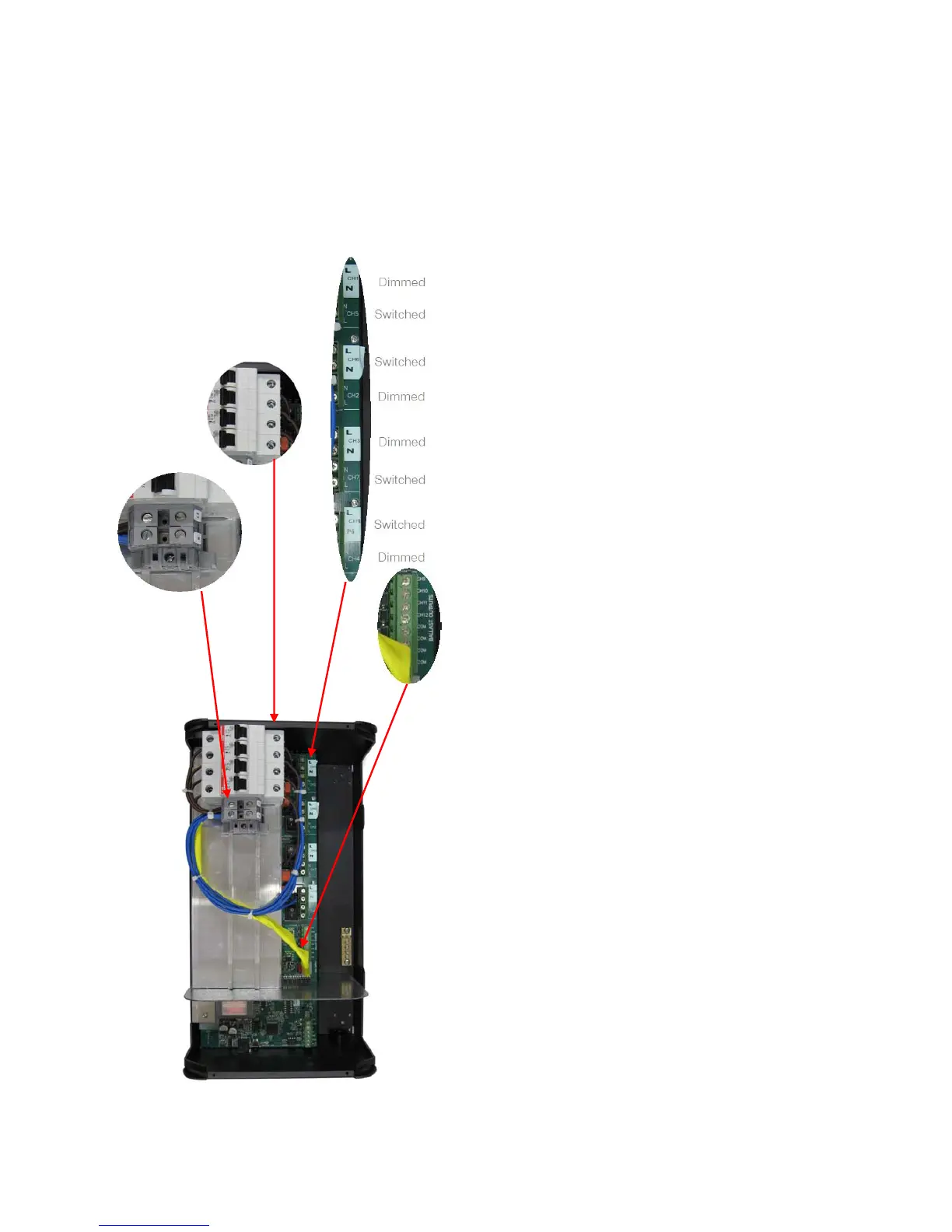
Supply Cables
The Phase & Neutral supply terminals are located
toward the middle of the enclosure. The supply
cables shall have a minimum capacity of 40A, to
prevent cable overheating.
Dimmed and Switched Load Cables
Dimmed and switched load cables shall be
terminated on 4 designated terminal blocks (one
Phase & Neutral for each channel), and an Earth
link located at the centre of the enclosure. These
connectors will accept up to 4mm
2
cables. It is
important that an individual output circuit is not
overloaded. Calculate the intended load, and
ensure that it is below the maximum capacity of
an individual channel. Channels 1 – 4 are dimmed
channels with a maximum capacity of 10 Amps
per channel. Channels 5 – 8 are Switched
channels, with a maximum capacity of 10 Amps
per channel, total load per 2 channels protected
by a single MCB is 10 Amps. The load neutral
cables shall be individually connected to the
neutral link terminals provided per channel with a
max of 10Amps per neutral terminal. Never use a
common neutral at a remote location.
Ballast Control Cables
Ballast Control cables shall be terminated on the
designated terminal block located directly below
the Load terminals. These terminals are labelled
CH9 to CH12, and can operate in tandem with the
corresponding Load Outputs, or can be
programmed to operate independently. 1-10V,
DSI or DALI broadcast control are software
configurable.
Emergency Lighting Connections
Connect emergency lighting circuit active to the
load side on the circuit breaker for the relevant
bank of 2 channels, as indicated by the front panel
markings next to the circuit breakers. Do not
remove any cables that may already be
terminated, make sure device is isolated before
removing cover.
Energising the Device
If it is necessary to energise load circuits before
any control cables are connected, it is acceptable
to energise the device and replace the cover
immediately, as the default factory programming
is to have all channels set to 100% output. If
there is no output on any or all channels, see the
“Troubleshooting” section (page 11). This device
shall be de-energised before terminating any
control or data cables.
1. Su