One Small Plate, Plate #2
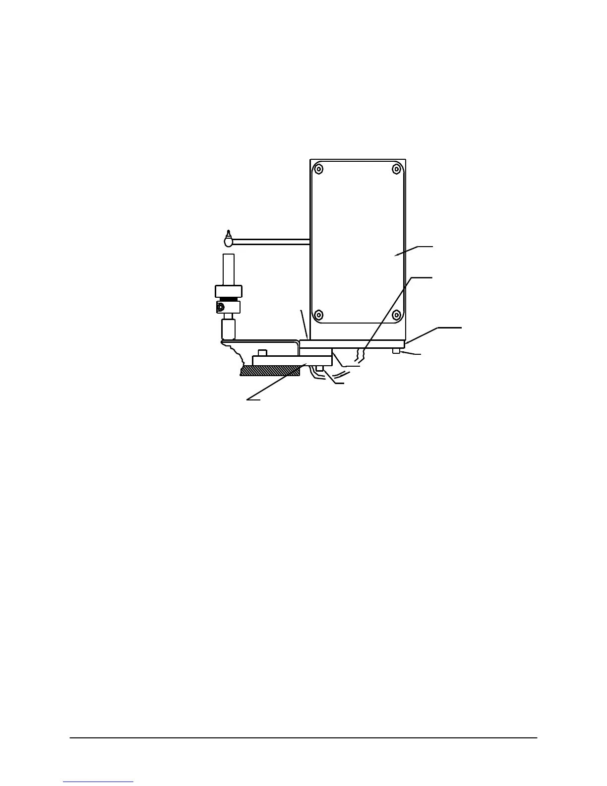
Installation Steps (See Figure 1);
1. Using two 5/8 " Reduced Head Socket Cap Screws & two #8 Lock Washers,
attach plates #1 & #2 to plate #3 (plate #3 is already attached to the MI).
Tighten the screws.
Encoder Housing
Two Reduced Head
#8-32 x 5/8" Long
Socket Cap Screws &
Two Lock Washers
Phone Jack Cable
Plate #1
Plate #2
Two #8-32 x 5/8" SHCS
Two Washers & Lock Wash
Figure #1
Two #8-32 x 1.25" SHCS
Two Washers & Lock Washers
Plate #3 (Already Mounted to MI)
2. Attach the Encoder Housing to the long plate (plate #1) using two 1.25" long
SHCS, two 5/8" long SHCS, 4 washers & 4 lock washers (washers first then
lock washers, i.e. lock washers under screw head).
Note for Pneumatic Lift Users: With the encoder arm in the down position,
lower the pneumatic lift. Move the arm up and down to check for clearance
with the pneumatic lift bucket. Clearance may be increased a small amount by
rotating the encoder housing before tightening the screws. If no clearance
exists and the arm hits the pneumatic lift bucket, contact Dynisco Polymer Test
before proceeding.
Tighten the screws
3. Plug the phone jack cable into the encoder housing.
4. Move the encoder arm into the down position.
5. Turn the power on.
6. Enable the Encoder by pressing the SETUP key. Browse the options until
you reach B FLAG and press EDIT. Press —› Quick Key so that ENCODR is
over the SELECT Quick Key. SELECT ENCODER and press ENTER to
accept. Press ESC to back out to the main menu.
Series 4000 Melt Indexer Operation Manual Getting Started
8