Page C-6
BODY
Repair and Service Manual
Read all of Section B and this section before attempting any procedure. Pay particular attention to all Notices, Cautions Warnings and Dangers.
B
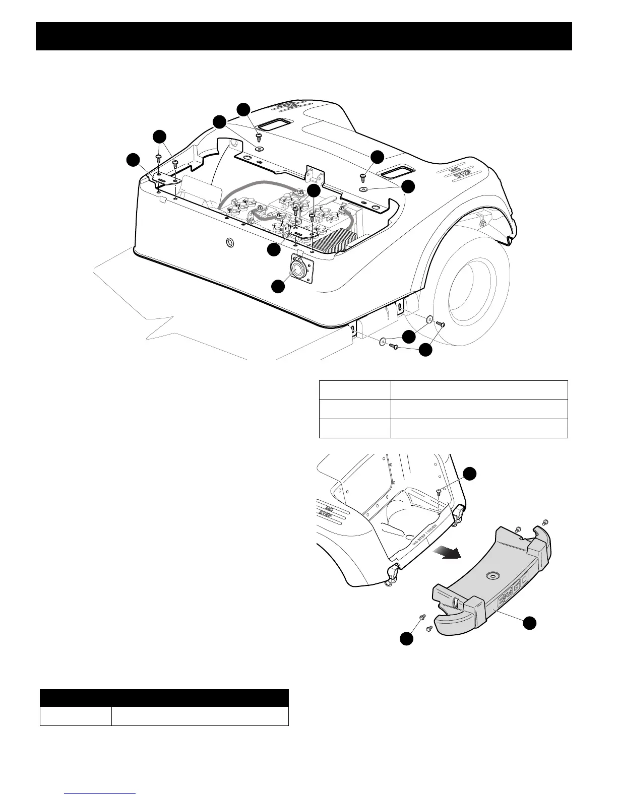
Fig. 13 Rear Body
3. Unplug the cord from the charger receptacle (30) to
the on board battery charger, disconnect the plug to
the accessory harness.
4. Remove two torx screws (33) securing each hinge
plate (32) along the front edge of the rear body then
remove both hinge plates.
5. Remove two inner torx screws (34) and washers (35)
from the back edge of seat opening in the rear body.
6. Remove four torx screws (36) and washers (37) from
the lower edge of the rear body, two on the driver side
and two on the passenger side.
7. Remove two torx screws (38) from the bagwell floor.
It is recommended that the removal of the rear body
is done using two people, one on each side of the
vehicle.
8. Lift the rear body, pivot the seat opening upward and
towards the back of the vehicle to clear the seat back
supports.
Reassemble in reverse order of removal. Replace
any worn or damaged hardware with new as
required. It is recommended that all locking nuts be
replaced after 5 removals
.
Fig. 14 Bagwell and Rear Bumper
ITEM TORQUE SPECIFICATION
33, 34 13 - 16 ft. lbs. (18 - 22 Nm)
36 26 - 44 in. lbs. (3 - 5 Nm)
38 2 - 4 ft. lbs. (4 - 6 Nm)
39 10 - 13 ft. lbs. (14 - 17 Nm)
38
39
40


 To Next Page