Page F-6
FRONT SUSPENSION AND STEERING
Repair and Service Manual
Read all of Section B and this section before attempting any procedure. Pay particular attention to all Noti4ces, Cautions, Warnings and Dangers.
B
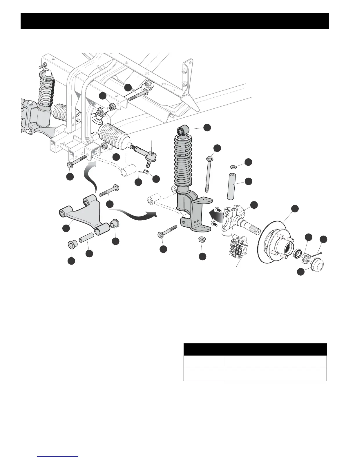
Fig. 7 Hub, Spindle, Strut and A-Arm Assemblies
A-Arm Assembly (Ref Fig. 7)
Tool List Qty.
Wrench, 15mm ............................................................ 1
Socket, 15mm.............................................................. 1
Ratchet ........................................................................1
Torque Wrench, ft. lbs.................................................. 1
Remove the front bumper as shown in the Body section
of this manual. Remove the front wheel(s) as described
in the Wheels and Tires section of this manual.
1. Remove the hex head bolt (11) securing the a-arm
(13) to the strut.
2. Remove bushings (14 & 16) from a-arm, being careful
to retain sleeve (15).
3. Inspect the sleeve (15) for wear or pitting; replace if
sleeve (15) shows signs of wear or pitting.
4. Remove two hex head bolts (17 & 18) securing the a-
arm to the frame brackets.
Reassemble in reverse order, replace worn or dam-
aged hardware as required.
Tie Rod End
Brake Caliper and Pads
4
1
11
16
15
14
13
17
2
8
22
20
18
20
19
21
5
6
9
7
10
3
ITEM TORQUE SPECIFICATION
11, 17, 18 20 - 25 ft. lbs (27 - 34 Nm)
19 20 - 25 ft. lbs (34 - 41 Nm)


 To Next Page