Page F-10
FRONT SUSPENSION AND STEERING
Repair and Service Manual
Read all of Section B and this section before attempting any procedure. Pay particular attention to all Noti4ces, Cautions, Warnings and Dangers.
B
spindle arm.
4. Repeat steps 3 through 5 for the remaining tie rod
end.
5. Remove the lower cross bolt securing the yoke to the
steering box pinion.
6. Loosen the upper cross bolt securing the yoke to the
intermediate shaft.
7. Remove the yoke from the steering box pinion by slid-
ing it up the intermediate shaft.
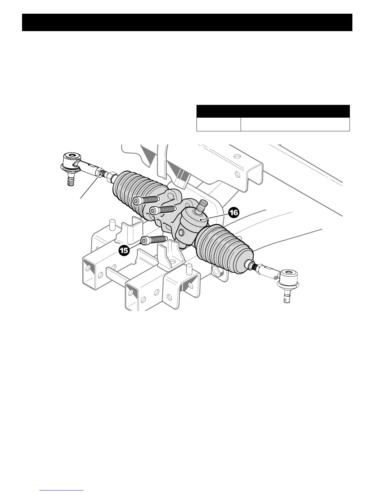
8. Remove three torx head screws (15) securing the
steering box (16) to the vehicle frame.
9. Remove steering box from the driver’s side of the
vehicle.
Reassemble in reverse order, replace worn or dam-
aged hardware as required.
Fig. 14 Steering Box
ITEM NO TORQUE SPECIFICATION
15 20 - 25 ft. lbs (27 - 34 Nm)


 To Next Page