P139-HD Audio System User Manual
GA063-3 Rev G 08/25/2015 Page
of 35
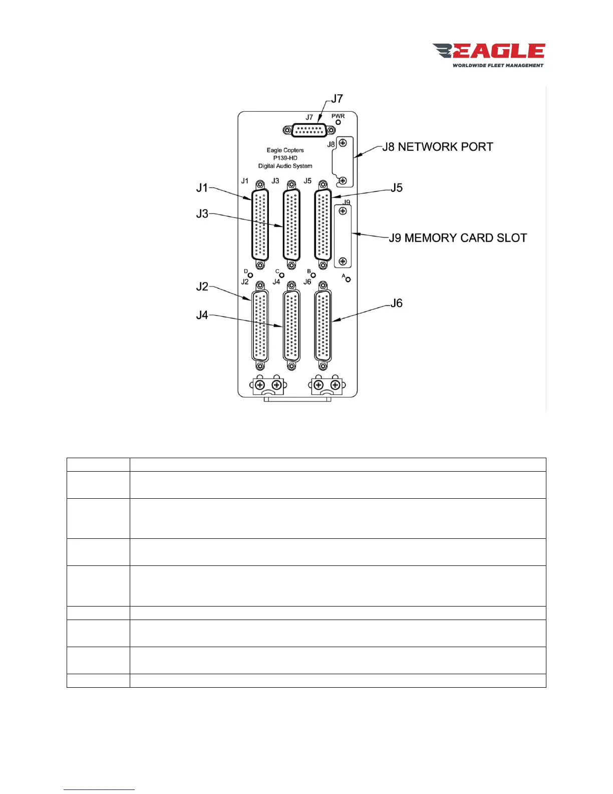
Figure 3 G13160 Front Panel
The G13160 front panel has nine connectors and five LEDs:
Radio Ports COM1 and XCVR3 – XCVR11. COM1 and XCVR11 have relays for the Pilot
Emergency Isolation Mode.
Pilot Headset and H/S3 – H/S7. Pilot Headset has relays for the Pilot Emergency Isolation
Mode and a dedicated COM1 Transmit Keyline.
Gnet Ports 1 and 2. Each port may connect to multiple control panels.
Radio Ports COM2 and XCVR12 – XCVR20. COM2 and XCVR20 have relays for the Co-
pilot Emergency Isolation Mode.
Co-pilot Headset and H/S8 – H/S12. Co-pilot Headset has relays for the Co-pilot
Emergency Isolation Mode and a dedicated COM1 Transmit Keyline.
Gnet Ports 3 and 4. Each port may connect to multiple control panels.
Radio Ports XCVR21 – XCVR30.
Headset Ports H/S13 – H/S18. Gnet Ports 5 and 6. Each port may connect to multiple
control panels.
Power and Ground Connections. Individual control lines for Pilot Emergency Isolation Mode
and Co-pilot Emergency Isolation Mode. Two control panel Dimmer input lines.
Ethernet port for accessing the Configuration Web Page.