Do you have a question about the Eastron SDM630MCT and is the answer not in the manual?
Lists measured parameters and password-protected setup screens.
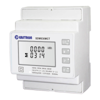
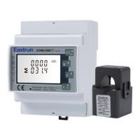
Explains CT configuration for 40mA output.
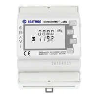
Details RS485 communication for remote monitoring.
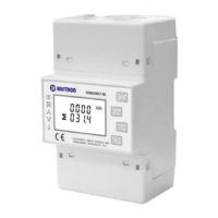
Displays initial device status and self-test results during startup.
Details phase-to-neutral and phase-to-phase voltage and current readings.
Covers frequency and total power factor measurements.
Details power factor readings for individual phases.
Displays instantaneous active power per phase in kW.
Displays instantaneous reactive power per phase in kVAr.
Displays instantaneous apparent power per phase in kVA.
Displays total active energy consumption in kWh.
Displays total reactive energy consumption in kVArh.
Displays imported active energy in kWh.
Displays exported active energy in kWh.
Displays imported reactive energy in kVArh.
Displays exported reactive energy in kVArh.
Explains methods for entering setup menus and parameters.
Details the process for entering numerical data in setup screens.
Setting the RS485 network address for communication.
Configuring the communication baud rate for RS485.
Setting the parity option for RS485 communication.
Configuring the stop bit setting for RS485 communication.
Setting the primary current for the current transformer (CT1).
Setting the secondary voltage for the voltage transformer (PT).
Configuring pulse output units to kWh or kVArh.
Setting the energy constant per pulse (e.g., Wh/VArh per pulse).
Setting the pulse width for outputs (e.g., 200ms).
Setting the integration period for maximum demand measurements.
Configuring the duration of the blue backlit display.
Selecting the type of power supply system being monitored.
Changing the unit's access password.
Resetting the maximum demand value for current and power.
Setting up correction for reversely connected current transformers.
Procedure for operating when phase A CT is reversely connected.
Lists all parameters the unit can monitor and display.
Details voltage and current measurement ranges and THD.
Specifies ranges for power factor, frequency, and demand.
Specifies ranges for active and reactive energy measurements.
Describes voltage and current input connections and CT rating.
Lists accuracy for various measurements like voltage, current, power.
Specifies voltage and consumption for auxiliary power supply.
Describes RS485, real-time energy output, and pulse output.
Explains configurable pulse output 1 (units, constant) and fixed pulse output 2.
Lists configurable RS485 parameters like baud rate, parity, stop bits, address.
Details variables affecting measurement errors and accuracy conditions.
Specifies operating temperature, humidity, altitude, vibration, and shock.
Provides physical dimensions and mounting details of the meter.
Wiring diagram for three-phase four-wire system using 3 CTs.
Wiring diagram for power supply from the grid.
Wiring diagram for auxiliary power supply.
Wiring diagram for three-phase three-wire system using 2 CTs.
Wiring diagram for power supply from the grid.
Wiring diagram for auxiliary power supply.
Wiring diagram for single-phase two-wire system using 1 CT.
Wiring diagram for power supply from the grid.
Wiring diagram for auxiliary power supply.
Key technical parameters of the current transformer.
Definitions of primary, secondary, and polar ends of the transformer.
Technical requirements for the transformer's construction and output.
Specifies current and phase error requirements for the transformer.
| Model | SDM630MCT |
|---|---|
| Category | Measuring Instruments |
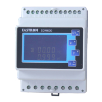
| Display | LCD |
| Frequency | 50/60Hz |
| Impulse Voltage | 6kV |
| Mounting | DIN rail |
| Power Measurement | Active, Reactive, Apparent |
| Communication Interface | RS485 |
| Operating Temperature | -25°C to +55°C |
| Storage Temperature | -40°C to +70°C |
| Input Voltage | 230/400V AC |
| Rated Voltage | 230/400V AC |
| Voltage Range | 176~276V AC (L-N) |
| Base Current | 1A, 5A |
| Maximum Current | 100A |
| Starting Current | 0.4% of In |
| Frequency Measurement Range | 45Hz - 65Hz |
| Pulse Output | Yes |
| Communication | RS485 Modbus RTU |
| Measurement Type | Voltage, Current, Power, Energy, Frequency, Power Factor |
| Current Measurement Range | 0.5A ~ 100A |
| Energy Measurement | Active, Reactive |
| Accuracy | Class 0.5S |
| Power Supply | Self-supplied |
| Type | Three-Phase Multi-Function Energy Meter |