Do you have a question about the Eastron SDM630-Mbus V2 and is the answer not in the manual?
Lists the parameters the unit can measure and display, including voltage, current, frequency, and power.
Describes the Mbus port and its use for remote monitoring and control via EN13753-3 protocol.
Details the unit's two pulse outputs for indicating real-time measured active and reactive energy.
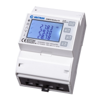
Explains the initial screen displays during power-up, including self-test and firmware information.
Describes how the U/I, M, P, and E buttons are used to navigate measurement screens.
Shows phase-to-neutral voltage measurements for 3-phase 4-wire and 3-phase 3-wire systems.
Displays current measurements for each individual phase (L1, L2, L3).
Presents phase-to-neutral voltage THD% for 3-phase 4-wire and 3-phase 3-wire systems.
Displays the overall system frequency (Hz) and total power factor (PF).
Shows the power factor for each individual phase (L1, L2, L3).
Indicates the peak active power demand recorded since the last reset.
Shows the peak current demand recorded since the last reset.
Displays the real-time active power consumption or generation in kW.
Displays the real-time reactive power consumption or generation in kVAr.
Displays the real-time apparent power (Volt-amps) in kVA.
Shows the total accumulated active (kW), reactive (kVAr), and apparent (kVA) power.
Displays the accumulated imported active energy in kWh.
Displays the accumulated exported active energy in kWh.
Displays the accumulated imported reactive energy in kVArh.
Displays the accumulated exported reactive energy in kVArh.
Shows the total accumulated active energy consumption or generation in kWh.
Shows the total accumulated reactive energy consumption or generation in kVArh.
Procedure to access the setup menu by pressing the E button for 3 seconds.
How to browse and select options within the setup menu using M, P, and E buttons.
Step-by-step guide for entering numerical values for settings like password.
Instructions on entering the default password and changing it.
Configures the time period in minutes for maximum demand measurement calculations.
Sets the time the display backlight remains active after the last button press.
Selects the type of power supply system (1P2W, 3P3W, 3P4W) being monitored.
Sets up pulse output 1 to represent total, import, or export energy (kWh/kVArh).
Chooses whether the pulse output represents kWh or kVArh.
Sets the energy value (e.g., 10 kWh/kVArh) represented by each pulse.
Configures the duration of the pulse output signal (e.g., 60ms, 100ms, 200ms).
Sets the Modbus RS485 address for communication, ranging from 001 to 250.
Configures the communication baud rate (e.g., 2.4k, 9.6k).
Sets the parity bit (EVEN, ODD, NONE) for serial communication.
Sets the number of stop bits (1 or 2) for serial communication.
Provides a function to reset the maximum demand value of current and power.
Lists all parameters the unit can monitor and display for various supply systems.
Provides specific ranges and limits for phase-to-neutral, phase-to-phase voltages, and current.
Details specifications for instantaneous power, frequency, and maximum demand.
Outlines the measurement ranges for active and reactive energy (imported/exported/total).
Describes the input connections and supported wiring configurations (1P2W, 3P3W, 3P4W).
Details the accuracy specifications for voltage, current, power, energy, and distortion.
Lists available interfaces for external monitoring: MBus, Pulse Output 1 & 2.
Specifies configurable pulse output 1 parameters and fixed pulse output 2.
Details MBus communication parameters configurable via the setup menu.
Specifies conditions (temperature, frequency, waveform) that affect measurement accuracy.
Lists operating temperature, storage temperature, humidity, altitude, and vibration limits.
Shows the physical size (height, width, depth) and DIN rail mounting details.
Illustrates the terminal connections for a 3-phase, 3-wire power supply system.
Illustrates the terminal connections for a 3-phase, 4-wire power supply system.
Illustrates the terminal connections for a single-phase, 2-wire power supply system.
| Type | Energy Meter |
|---|---|
| Mounting | DIN rail |
| Communication | M-Bus |
| Current | 5A |
| Maximum Current | 100A |
| Frequency | 50/60Hz |
| Frequency Measurement Range | 45-65Hz |
| Display | LCD |
| Operating Temperature | -25°C to +55°C |
| Storage Temperature | -40°C to +70°C |
| Protection Class | IP51 (front), IP20 (terminals) |
| Phase | Three Phase |
| Voltage | 230/400V AC |
| Power Factor Measurement Range | -1 to 1 |
| Accuracy | Class 1 |
| Accuracy Class | Class 1 |
| Humidity | Up to 95% non-condensing |
| Standards Compliance | IEC 62053-21 |
| Voltage Measurement Range | 176 ~ 276V AC (L-N), 304 ~ 480V AC (L-L) |
| Power Supply | Self-powered |