Do you have a question about the Eastron SDM630MCT Series and is the answer not in the manual?
Lists the measurable parameters of the unit, including voltage, frequency, current, and energy.
Details on password-protected configuration options like changing password and system selection.
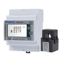
Information on configuring the unit with CT ratio for primary and secondary current.
Details on using the RS485 serial port with Modbus RTU protocol for remote monitoring.
Describes the two pulse outputs for active and reactive energy measurement.
Explains how under-range ('0') and over-range ('-') are displayed on the unit.
Defines the threshold values for voltage, current, and power for under-range and over-range.
Describes the initial screens displayed when the unit powers on.
Explains how the buttons operate to navigate measurement screens.
Displaying total frequency in Hz and overall power factor.
Displaying power factor for each individual phase.
Displaying the maximum current and power demand.
Displays instantaneous active, reactive, and apparent power.
Displays total active, reactive, and apparent power.
Displays total active energy (kWh) and reactive energy (kVArh).
Displays imported and exported active energy (kWh).
Displays imported and exported reactive energy (kVArh).
Displays total active and reactive energy for the 2T model.
Displays T1 and T2 active/reactive energy for the 2T model.
Displays total active energy in kWh for the MT model.
Displays T1 through T4 active energy in kWh for the MT model.
Displays total reactive energy in kVArh for the MT model.
Displays T1 through T4 reactive energy in kVArh for the MT model.
How to enter the default password '1000' to access set-up.
Procedure to exit set-up mode and return to measurement screen.
Steps for navigating menus, selecting items, and confirming choices.
Details how to enter numerical values for settings like password or ratios.
Selecting the 'Change Password' option from the set-up menu.
Setting and confirming each digit of the new password.
Finalizing the password change process and exiting the routine.
Setting the integration period for maximum demand measurements.
Confirming the selected demand integration time.
Function to set the blue backlit lasting time.
Choosing and confirming the power supply system type.
Selecting and setting the secondary current (CT2 1A or 5A).
Setting the CT ratio value for primary to secondary current.
Selecting and setting the secondary voltage (PT2 100 to 500V).
Choosing whether pulse output represents kWh or kVArh.
Sets the energy represented by each pulse.
Choosing the pulse rate value and confirming the setting.
Sets the pulse width for active or reactive energy.
Confirming the selected pulse width and returning to the menu.
Setting the Modbus RTU network address for the unit.
Setting the communication baud rate for RS485 Modbus RTU.
Setting the parity option for RS485 Modbus RTU communication.
Selecting the specific parity (EVEN, ODD, NONE).
Setting the stop bit option for RS485 Modbus RTU communication.
Procedure to reset the maximum demand value of current and power.
Setup for correcting reverse connected current inputs.
Adjusting the Phase A connection setting from 'Frd' to 'Rev'.
Setting the date for the SDM630MCT-MT display.
Confirming the date setting and its format (YYYY-MM-DD).
Setting the time for the SDM630MCT-MT display.
Confirming the time setting and its format (HH-MM-SS).
Information about tariff settings for the SDM630MCT-MT display.
Specifications for measured parameters, voltage, and current.
Specifications for power factor, frequency, and maximum demand.
Specifications for power, energy measurements, and inputs.
Accuracy details for voltage, current, power, energy, and THD.
Details on RS485 communication and pulse output interfaces.
Details on the unit's two passive pulse outputs.
RS485 communication parameters configurable via Set-up menu.
Variables affecting measurement errors and their reference conditions.
Environmental operating conditions for the meter.
Warning about hazardous voltages and need for qualified personnel.
Requirement for external fuse and safety for CT connections.
Physical dimensions of the energy meter unit.
Wiring diagram for three phase four wire system installation.
Wiring diagram for three phase three wire system installation.
Wiring diagram for single phase two wire system installation.
Wiring diagram for single phase (split-phase) three wire system installation.
| Model | SDM630MCT Series |
|---|---|
| Category | Measuring Instruments |
| Voltage Measurement | True RMS |
| Current Measurement | True RMS |
| Operating Temperature | -25°C to +55°C |
| Storage Temperature | -40°C to +70°C |
| Frequency | 50/60Hz |
| Accuracy Class (Active Energy) | Class 1.0 |
| Accuracy Class (Reactive Energy) | Class 2.0 |
| Display | LCD with backlight |
| Communication | Modbus RTU via RS485 |
| Humidity | < 95% RH, non-condensing |
| Power Measurement | Active Power, Reactive Power, Apparent Power |
| Energy Measurement | Active Energy, Reactive Energy |