Do you have a question about the Eastron SDM630-Modbus V2 and is the answer not in the manual?
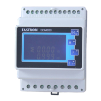
The unit can measure and display voltage, frequency, current, power, and energy parameters.
Details the RS485 serial port with Modbus RTU protocol for remote monitoring and control.
Explains the two pulse outputs for clocking measured active and reactive energy.
Details selecting and viewing voltage and current display screens using the device buttons.
Explains how to view frequency, power factor, maximum power, and maximum current demand.
Details viewing instantaneous power (kW, kVAr, kVA) and total/imported/exported energy (kWh, kVArh).
Instructions on how to enter the set-up mode by pressing the E button for 3 seconds.
Details password entry for setup access and general menu navigation using buttons.
Describes the process for entering numerical digits individually for settings like password.
Step-by-step guide to changing the unit's password using the device interface.
Explains how to set the period for integrating readings for maximum demand measurement.
Details how to configure the duration for which the display backlight remains active.
Instructions for setting the type of power supply being monitored (e.g., 1p2w, 3p3w, 3p4w).
Allows configuration of pulse output 1 for energy (kWh/kVArh) active or reactive measurements.
Explains how to set the energy value (e.g., 10kWh) represented by each pulse output.
Details setting the pulse width for the output signals (e.g., 200ms, 100ms, 60ms).
Instructions for setting the unique address for RS485 communication (001 to 247).
Details selecting the communication speed (e.g., 9.6k, 19.2k) for RS485.
Explains how to set the parity bit (EVEN, ODD, NONE) for RS485 communication.
Details setting the number of stop bits (1 or 2) for RS485 communication.
Explains how to reset the maximum demand values for current and power.
Lists all parameters monitored and displayed by the unit across different supply systems.
Details measured input specifications and accuracy levels for voltage, current, power, and energy.
Describes external monitoring interfaces like RS485 and pulse outputs, including Modbus RTU configuration.
Lists variables affecting measurement errors and environmental operating conditions.
Illustrates wiring connections for a three-phase, three-wire system.
Illustrates wiring connections for a three-phase, four-wire system.
Illustrates wiring connections for a single-phase, two-wire system.
| Base Current (Ib) | 10A |
|---|---|
| Maximum Current (Imax) | 100A |
| Frequency | 50/60Hz |
| Impulse Voltage | 6kV |
| Communication Interface | RS485 |
| Protocol | Modbus RTU |
| Display | LCD |
| Operating Temperature | -25°C to +55°C |
| Storage Temperature | -40°C to +70°C |
| Mounting | DIN rail |
| Rated Voltage (Un) | 230V/400V |
| Power Supply | 230V AC (L-N) |
| Power Consumption | <5VA |
| Frequency Measurement Range | 45 ~ 65Hz |
| Accuracy | Class 1 |
| Baud Rate | 1200 ~ 38400 bps |
| Weight | 0.3 kg |
| Protection Class | IP51 (indoor use only) |
| Voltage Measurement Range | 176V to 276V (phase to neutral) / 304V to 480V (phase to phase) |
| Voltage Range | 80% to 120% of Un |