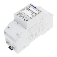
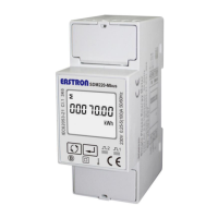
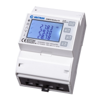
Do you have a question about the Eastron SDM230-LoRaWAN and is the answer not in the manual?
Details the measurable and displayable characteristics of the unit and its password-protected setup screens.
Explains the two passive pulse outputs, their configurability, and pulse constants.
States that the meter implements Class C functionality and uploads messages after receiving data from the network.
Describes the customizable active upload mode for automatic parameter uploading with configurable interval time.
Explains the LoRaWAN network joining process, activation ways (OTAA/ABP), and required information for successful gateway connection.
Details LoRaWAN communication protocol, data placement in the payload, and the format of standard LoRaWAN messages.
Configures the type of pulse output, with default and available range options.
Sets the energy value represented by each pulse, with default and range options.
Sets the duration of the pulse output signal, with default and range options.
Configures the integration time for demand measurements, with default and range options.
Sets the time interval for automatic scrolling through displayed parameters.
Sets the duration the backlight remains active, with default and range options.
Resets demand and resettable kWh/kVArh information.
Allows changing the password for accessing settings, with default and range options.
Details join parameters for OTAA and ABP modes, such as DevEui, DevAddr, AppEui.
Shows the status of the meter's connection to the gateway, indicating success or failure.
Details join parameters for OTAA (DevEui, AppEui, Appkey) and ABP (DevAddr, NwkSKey, AppSKey) modes.
Allows selection between OTAA and ABP activation modes for network joining.
Allows the meter to re-join the network if the connection is lost.
Configures automatic upload of data and sets the interval time for checking gateway connection.
Configures a delay for joining the LoRaWAN network after booting or ON/OFF.
Sets the time period for considering the meter offline if no message is received from the gateway.
Enables the meter to request confirmation of message reception from the LoRaWAN network.
Details electrical specifications including measurement accuracy, data update rate, input voltage, and current.
Details mechanical specifications such as weight, dimensions, mounting, and material.
Lists environmental parameters like operating temperature, humidity, altitude, and vibration.
Outlines safety precautions, measurement categories, input requirements, and protective classes.
Details communication standards, frequency bands, LoRaWAN classes, coding format, and distance.
Covers safety guidelines for installation, including design standards and installation category.
Provides guidance on EMC installation requirements to ensure proper operation and avoid interference.
Lists crucial safety warnings regarding hazardous voltages, qualified personnel, and terminal accessibility.
Shows the physical dimensions of the unit with a diagram.
Illustrates the wiring connections for the unit, including input/output terminals.
| Brand | Eastron |
|---|---|
| Model | SDM230-LoRaWAN |
| Category | Measuring Instruments |
| Language | English |

