EasyManua.ls Logo

Eastron Smart X96-5J User Manual

Eastron Smart X96-5J
38 pages
To Next Page IconTo Next Page
Page #1 background imageLoading...
Page #1 background image
EASTRON SMART X96-5 F/G/H/I/J User Manual V1.
9
1
SMART X96-5 -F/G/H/I/J
MULTI-FUNCTION POWER ANALYSER
Multi-parameter Measurements
Up to 63
rd
THD and IHD
RS485 Modbus RTU
Ethernet TCP Gateway
Multi-tariffs
Digital Input/Output
Accuracy Class 0.5s
Bar Graph for Power Indication
Backlit LCD Display for Full Viewing Angles
Push-in Installation and Plug-in Connection
Question and Answer IconNeed help?

Do you have a question about the Eastron Smart X96-5J and is the answer not in the manual?

Eastron Smart X96-5J Specifications

General IconGeneral
BrandEastron
ModelSmart X96-5J
CategoryMeasuring Instruments
LanguageEnglish

Summary

Unit Characteristics

1.2 Password Protected Setup Screens

Details the password-protected configuration options available on the unit.

Additional Unit Features

1.3 CT and PT Configuration

Specifies the Current Transformer (CT) and Potential Transformer (PT) ranges supported by the unit.

1.4 RS485 Modbus RTU Communication

Describes the use of the RS485 serial port with Modbus RTU protocol for remote control.

1.5 Ethernet TCP/IP Connectivity

Explains the Ethernet TCP/IP communication port for data transfer and network integration.

Additional Button Display Parameters

3.3 Individual Harmonic Distortion

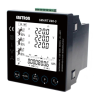
Explains how to check voltage and current harmonic distortion using specific buttons.

4. Setting-Up and Configuration

Communication & Network Configuration

Covers communication parameters (COMS, TCP/IP) and network settings.

Transformer (CT/PT) Configuration

Details the configuration settings for Current and Potential Transformers.

Demand and Time Setting Options

Covers demand settings and time-related options like backlight and scroll.

System and Input/Output Configuration

Covers system type, connection, digital inputs, and outputs.

Accessing Setup Menus

4.1 Password Entry

Explains how to enter the password to access setup mode.

4.2.1 Setting Modbus Address

Details how to set the Modbus address for RS485 communication.

Communication Settings Details

4.2.2 Configuring Baud Rate

Explains how to set the baud rate for communication.

4.2.3 Setting Parity Options

Explains how to set the parity for communication.

Further Communication Settings

4.2.4 Stop Bit Configuration

Explains how to set the stop bits for communication.

4.3 Current Transformer (CT) Setup

Introduces the Current Transformer (CT) setup menu.

CT and PT Setup Procedures

4.3.1 Setting CT2 Secondary Current

Explains how to set the secondary current input for CT2.

4.3.2 Setting CT1 Primary Current

Explains how to set the primary current input for CT1.

4.4 Potential Transformer (PT) Setup

Introduces the Potential Transformer (PT) setup menu.

PT Setup Procedures

4.4.1 Setting PT2 Secondary Voltage

Explains how to set the secondary voltage input for PT2.

4.5 Demand Configuration

Explains how to set the demand measurement period in minutes and calculation modes.

Demand Configuration Details

Time and Display Settings

Time and Clock Settings

System Type and Connection Settings

System Connection and Security Settings

Digital Input and Output Configuration

Digital Output (DO) Configuration

DO-1 Specific Settings and Alarms

DO Alarm and Threshold Settings

4.10 Ethernet Communication Settings

Introduction to Ethernet Settings

Introduces settings for Ethernet communication parameters.

Advanced Ethernet Configuration

Event Viewing and Reset Functions

4.12 Reset Functions

Introduces the reset function for various data.

5. Specifications

5.1 Electrical Characteristics & Accuracy

Details the electrical characteristics, measurement accuracy, and input ranges of the unit.

Model-Specific Features and Maintenance

6. Maintenance Guidelines

Provides general guidelines for maintaining the unit in normal use.

Battery Replacement and Installation

7. Installation Instructions

Provides instructions for installing the unit in a panel.

7.1 Safety Compliance

Details safety compliance with IEC 61010-1.

Installation Requirements and Precautions

7.2 EMC Installation Requirements

Offers guidance on installation to ensure proper EMC performance.

Related product manuals