APPENDIX #1
36
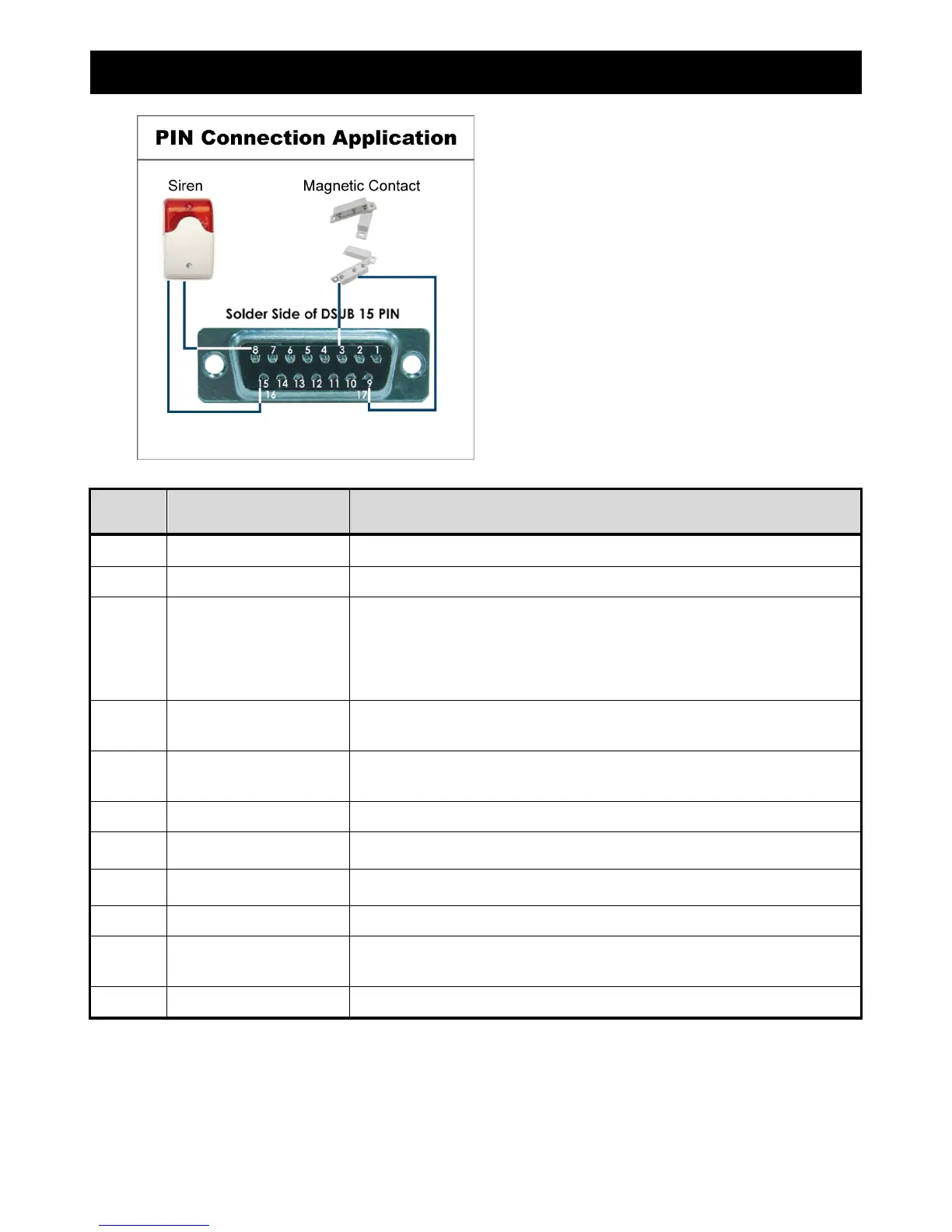
APPENDIX 1 DUSB PIN CONFIGURATION
PIN FUNCTION DESCRIPTION
1
PIN OFF
2
PIN OFF
3 ~ 6
ALARM INPUT
To connect the wire from ALARM INPUT ( PIN 3 -- 6 ) to GND ( PIN 9 ) connector, DVR will
start recording and the buzzer will be on.
*“MENU” -> “ADVANCE” -> “DETECTION” -> “DETECTION SETUP” -> “ALARM” is set to “N.C.”:
When the alarm input signal is “N.C.”, the unit starts to record and buzzer.
*“MENU” -> “ADVANCE” -> “DETECTION” -> “DETECTION SETUP” -> “ALARM” is set to “N.O.”::
When the alarm input signal is “N.O.”, the unit starts to record and buzzer.
7
EXTERNAL ALARM NC
Under the normal operation, COM connects with NC and disconnects from NO. But when any
alarm is triggered, COM disconnects with NC and connects with NO.
Attention: The voltage restriction is under DC24V 1A.
8
EXTERNAL ALARM NO.
Under the normal operation, COM disconnects with NO. But when any alarm is triggered,
COM connects with NO.
Attention: The voltage restriction is under DC24V 1A.
9
GND
Signal GND
10
RS485-B
DVR can be controlled remotely by the keyboard of PC by using RS-485 serial communication
signals.
11
RS485-A
DVR can be controlled remotely by the keyboard of PC by using RS-485 serial communication
signals.
12 ~ 14
PIN OFF
15
EXTERNAL ALARM COM
Under the normal operation, COM disconnects with NO. But when any alarm is triggered,
COM connects with NO.
Attention: The voltage restriction is under DC24V 1A.
16 ~ 17
GND
Earth GND
Magnetic Contact: When the magnetic
contact is opened, the alarm will be tri
ered
and the recording is on.
Siren: When the DVR is triggered by
alarm or motion, the COM connects with NO
and the siren with strobe starts wailing and