English EasyN IP Camera User Manual
www.easyn.com MFE-E-A3
5
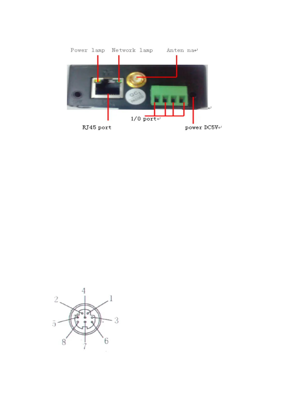
2.1. Interface
The back of a non-extended line IP Camera:
Power Supply Light: constantly on when power is on
Network light: constantly flashing which indicates data transmission when power is
on.
Ethernet interface: RJ-45 interface.
I/O interface: 1 for alarm input, connect 3 & 4 these two terminals (input terminal
grounding, low level effective trigger); 1 for TTL control input, connect
1& 2 these two terminals.
Power input interface: connect directly to 5V current Power
Extension line IP Camera:
Power: direct current 5V.
GPIO alarm interface: accept external connection linking to alarm equipment (for
example: door magnet, infrared)
Reset line: Short circuit the two lines to power off, then power on for 10 seconds to
return back to default setting
Ethernet interface: RJ-45 network interface.
Backup: follow-up product extend interface.
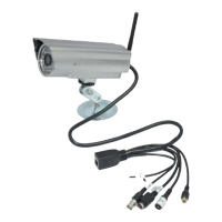
About GPIO alarm interface (S terminal) definition:
1# +DC12V
2# RS485(A)
3# Earth(GND)
4# IO2 (OUT PUT)
5# RS485 (B)
6# IO1 (IN PUT)
GND: Ground,alarm input ground,RS485
ground
RS485: RS485 control interface,left
connection RS485 negative right connection RS485 positive. connect to P/T decoder,
support various PTZ protocol.