2.5 MOUNTING
1. Select a mounting location that will provide suitable strength, rigidity
and space (per Section 2.1) for supporting the ACE Series system
and all contained wiring.
2. Refer to Section 2.2 for approximate weights and Section 2.4 for
dimensions.
3. For enclosure sizes 1 & 2, install two (2) 5/8” on the left side. For
enclosure size 3, install four (4) 7/8” bolts through mounting rails,
then proceed to Step 8.
4. Tap each of the four (4) mounting feet with a mallet to ensure tight
assembly.
5. Align enclosure with the two (2) left side mounting feet engaged
with the mounting bolts on selected mounting surface.
6. Tighten two (2) bolts on left side.
7. Install two (2) 7/8” bolts on right side and tighten.
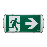
8. After enclosure is positioned and secured in its permanent location,
pull wires into the ACE Series system, making sure that they are
long enough to make the required connections.
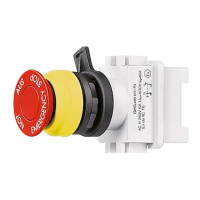
2.6 SHROUD INSTALLATION
1. Remove rubber caps from explosionproof filters.
2. Insert threaded rods into the explosionproof filters. Leave 3-5/8 of
threaded rod exposed.
3. Place shroud over explosionproof filters and threaded rod, with
shroud opening facing back of enclosure. See Figure 2.
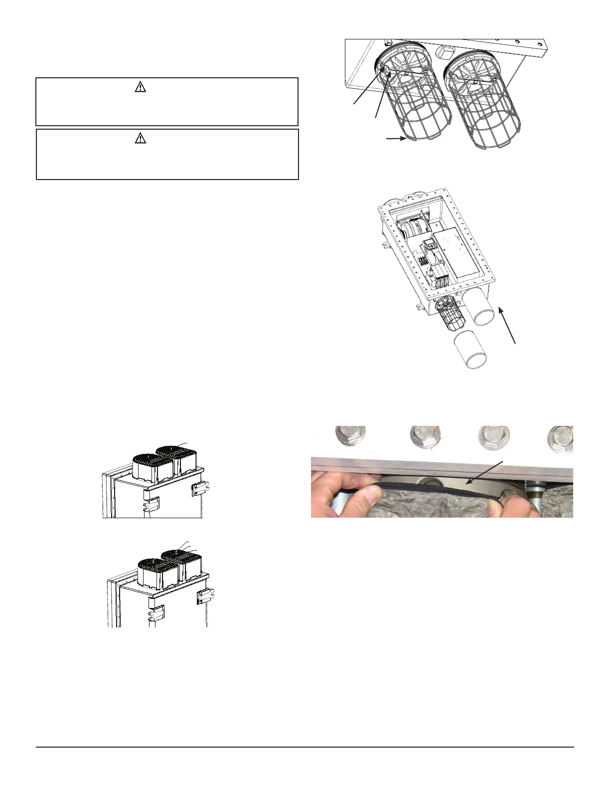
4. Insert washer and nuts onto end of threaded rod and tighten
securely until shroud is firmly contacting the top wall of the
enclosure. See Figure 3.
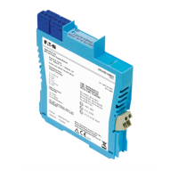
2.7 PRE-FILTER INSTALLATION
1. Remove rubber caps from explosionproof filters.
2. Install wire guard using the bracket, screw and lock washer provided
to the bottom filter(s).
3. Align guard with notches within the bracket as shown.
4. Tighten screw.
5. Slip pre-filter mesh over guard.
6. Be sure to stretch pre-filter elastic band completely around the
explosionproof filter and seat the elastic band on the filter’s threads.
This will ensure all air flow to the bottom filters passes through the
pre-filters.
3. ELECTRICAL INSTALLATION
3.1 ENCLOSURE GROUNDING - INTERNAL/
EXTERNAL
Grounding and bonding of the conduit and equipment is required by the
National Electrical Code
®
. A grounding conductor must be connected to
the grounding lugs furnished.
Determine the type of distribution systems to be used that will comply
with NEC requirements and ensure grounding continuity.
All conductive equipment that enclose the electrical conductors or
attached equipment or forming part of such equipment must be
grounded. A permanent connection must be made between all
such equipment and the earth. Refer to Section 5.3 for the torque
requirements of all terminations within this device.
CAUTION
To avoid cooling system malfunction, cooling system failure and
personnel injury, be sure to mount the enclosure as depicted in
Section 2.1.
CAUTION
To avoid cooling system malfunction, cooling system failure and
personnel injury, be sure to mount the enclosure in a shaded area to
avoid direct sunlight.
IF 1767 • 09/15 Copyright
©
2015, Eaton’s Crouse-Hinds Division Page 5
ACORN NUT
LOCKING NUT
WASHER
Figure 3
Figure 2
Detail View
Notch
Bracket
Guard
Explosionproof
Filter
 Loading...