EasyManua.ls Logo

Eaton Airflex CB Series - User Manual

Eaton Airflex CB Series
23 pages
Print Icon
To Next Page IconTo Next Page
Loading...
CB 4000
Installation, Operation
and Maintenance of
Airflex
®
CB Element
Assemblies
June,1990
(Revised: August, 2005)
203674
©
Copyright Eaton Corp., 2005. All rights reserved.
Caution:
UseOnlyGenuineAirflex
Replacement Parts
The Airflex Division of Eaton Corporation recommends the use of
genuine Airflex replacement parts. The use of non-genuine Airflex
replacement parts could result in substandard product performance,
and may void your Eaton warranty. For optimum performance, contact
Airflex:
In the U.S.A. and Canada: 1-800-AIRFLEX (247-3539)
Outside the U.S.A. and Canada: (216) 281-2211
Internet: www.airflex.com
Warning
Forward this manual to the person responsible
for Installation, Operation and Maintenance of
the product described herein. Without access
to this information, faulty Installation, Operation
or Maintenance may result in personal injury or
equipment damage.
StockCheck.com
Downloaded from StockCheck.com
Question and Answer IconNeed help?

Do you have a question about the Eaton Airflex CB Series and is the answer not in the manual?

Overview

The Airflex CB Element Assembly is a versatile air-actuated clutch or brake designed for a wide range of industrial applications, including high-speed, cyclic operations, coupling, and general power transmission. It is notable for its self-adjusting nature, which automatically compensates for lining and drum wear, eliminating the need for lubrication or manual adjustment.

Function Description:

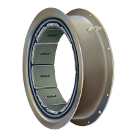
The core of the CB element's operation lies in its neoprene and cord actuating tube, bonded to an outer steel rim. Friction shoe assemblies (FSAs) are attached to the tube's inside diameter with shoe pins, secured by lockwires. When air pressure is applied to the actuating tube, it inflates, uniformly forcing the friction shoe assemblies against a drum. In clutch applications, where the CB element is attached to a driving shaft via a spider, torque is transmitted from the rim/tube structure to the friction shoe assemblies, and then through the friction couple to the drum mounted on the driven shaft. For brake applications, the element is attached to a rigid reaction bracket or machine frame, and the drum is attached to the shaft to be stopped. Upon exhaustion of actuating air, the tube's resiliency, aided by centrifugal force in clutch applications, retracts the shoes, ensuring total disengagement. The element's design allows the actuating tube to absorb damaging shock loads, contributing to its durability.

Important Technical Specifications:

  • Sizes: Available for drum diameters ranging from four inches through 45 inches. The element size designation indicates the nominal outside drum diameter in inches, the clutch model (CB series), and the width of the friction material. For example, "12CB350" signifies a 12-inch nominal drum diameter, CB series, and 3.5-inch wide friction material.
  • Maximum Applied Air Pressure: 110 psig (7.5 bar). Operation at pressures exceeding this limit may result in damage to the element. Consultation with the factory is required for higher pressure applications.
  • Drum Wear Limits: The maximum allowable wear on the drum diameter varies by element size, from 0.09 inches (2mm) for 4CB200 through 14CB400, up to 0.25 inches (6mm) for 45CB525. Operation with a drum worn or machined below the minimum allowable diameter will damage element components.
  • Shaft Alignment Tolerances:
    • Parallel Alignment (Offset): Not to exceed 0.010 inch (0.254mm) Total Indicator Reading (0.005 in. (0.127mm) maximum offset).
    • Angular Alignment (Gap): Not to be exceed 0.0005 inch per inch (0.0005mm/mm) diameter at which readings are taken.
    • Exceeding these limits will lead to accelerated wear of element components, severe vibration, and/or overheating due to dragging friction shoes when disengaged.
  • Fastener Torque: All mounting fasteners must be Grade 2 or better. Torque values for element to spider and drum to hub connections vary by element size, ranging from D 7 (10) ft-lb (Nm) for 4CB200 to L 163 (221) ft-lb (Nm) for 45CB525. Dual assemblies use the same values.
  • Friction Material: Non-asbestos friction material is used. A short "wear-in" period is required for initial rated torque development.
  • Dual Units: For applications with limited diametral space or requiring higher torque than a single element can transmit, CB elements size 12CB350 and larger can be supplied as dual units.

Usage Features:

  • Self-Adjusting: Automatically compensates for lining and drum wear, eliminating the need for manual adjustments.
  • No Lubrication Required: Simplifies maintenance and reduces operational costs.
  • Shock Load Absorption: The neoprene and cord actuating tube absorbs damaging shock loads, enhancing durability.
  • Torque Limiting Device: By limiting applied air pressure, the element can act as a torque limiting device, providing overload protection.
  • Regulated Engagement: A flow control valve in the air supply line can be adjusted to restrict airflow for cushioned engagement, while allowing free flow for rapid disengagement.
  • Mounting Arrangements: Supports various configurations including gap-mounted (element on driving shaft, drum on driven shaft), close-mounted (for limited shaft-to-shaft clearance), brake applications (element on reaction bracket, drum on shaft to be stopped), sheave clutch packages (built-in rotorseal and sealed ball bearings), and engine-mounted applications (clutch element on spider, drum on flywheel/bullgear). Specific drawings are available from Airflex for different arrangements.
  • Air Control System: A typical system includes a rotorseal, flow control valve, solenoid valve, relief valve, pressure gauge, pressure switch, check valve, pressure regulator, tank drain, and filter. The air receiver tank should be located close to the rotorseal (within five feet) for consistent response. Full-size piping and valves consistent with rotorseal size are recommended, with minimal elbows. Poppet-type solenoid valves are preferred over spool valves. An air line lubricator is not required, but if used, it must be a non-adjustable, mist-type.

Maintenance Features:

  • Periodic Inspection:
    • Air Control Components: Check for proper adjustment, correct safety pressure switch settings, and repair air leaks.
    • Friction Shoe Assembly Lining Wear: Linings must be replaced as a complete set when worn to a minimum allowable thickness of 1/16" (1.5mm), except for 4CB200 elements, which require replacement of the entire element when worn to 1/32" (0.8mm). Operation with worn friction material will damage the drum.
    • Contamination: Protect the element from oil, grease, or excessive dust, as contamination reduces torque and causes slippage and overheating. Oil or grease contamination requires disassembly for cleaning; saturated linings must be replaced. Dust accumulation can be vacuumed. Do not use compressed air to blow dust, as it may irritate the respiratory system.
  • Drum Diameter Wear: Periodically check the drum's outside diameter against specified wear limits. Minor heat-checking can be removed by machining. Operation with a worn or machined drum below minimum allowable diameter will damage element components.
  • Air Actuating Tube: Inspect for damage from excessive heat, hardening, charring, or blisters (indicating ply separation). A damaged tube requires replacement of the entire element.
  • Friction Shoe Surface: Glazed linings can be lightly sanded if they do not contain asbestos. If asbestos is present (indicated by green and yellow stripes with brass flakes), linings must be removed and disposed of properly with appropriate precautions. Always wear approved safety equipment when working with friction material.
  • Uneven Friction Lining Wear: May indicate a worn drum or misalignment.
  • Contamination of Friction Shoes: Mild oil or grease contamination can be removed with a solvent (following safety precautions). Linings charred from excessive heat must be replaced.
  • Removal of Element Assembly and Drum: Before removal, ensure machinery is in a safe condition. Match mark the element to the spider and the drum to the drum hub. Disconnect the element from the spider, support the element and drum with an overhead support, then remove fasteners attaching the drum to the drum hub and hoist the assembly out.
  • Disassembly of Dual Element: Lay the element on a clean, level surface. Disassemble the long air tube group, then remove fasteners connecting individual elements.
  • Removal of Spider and Drum Hub: Puller holes are provided. Heating the hub or spider uniformly to 250°F (121°C) is usually required to expand the bore for removal. Avoid "hot spots" when using torches.
  • Friction Shoe Replacement: Remove old shoe pin lockwires and pins, then remove old shoe assemblies. Insert new shoe assemblies and pins (heads on mounting flange/air connection side). Slide new lockwires through pin holes, ensuring the scallop points away from friction material, securing one friction shoe per two pins. Center the lockwire and bend ends inward around the shoe pin.
  • Spare Parts Storage: Element assemblies must be stored flat to prevent rims from going out-of-round. Drums must be stored open end down in a dry environment to prevent roundness issues.
  • Ordering Information: Refer to the product nameplate for information when ordering parts or seeking technical assistance. If the nameplate is unavailable, note the mounting arrangement, drum diameter, rim style, and air connection configuration.

Eaton Airflex CB Series Specifications

General IconGeneral
BrandEaton
ModelAirflex CB Series
CategoryIndustrial Equipment
LanguageEnglish

Related product manuals