Do you have a question about the Eaton PDI WaveStar TFA STS 250-600A and is the answer not in the manual?
| Category | Industrial Equipment |
|---|---|
| Type | Static Transfer Switch (STS) |
| Model | WaveStar TFA STS 250-600A |
| Manufacturer | Eaton |
| Current Rating | 250-600A |
| Application | Power Distribution |
| Features | advanced monitoring |
Explains the purpose and core functions of the Static Transfer Switch.
Details environmental, storage, and other technical specifications for the unit.
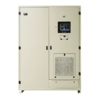
Illustrates the physical arrangement and key components of the STS unit.
Procedures for inspecting and verifying the delivered STS unit upon arrival.
Guidelines for safely moving and unpacking the STS unit and its components.
Steps for visually inspecting internal connections and components before installation.
Covers placement information, clearances, and mounting procedures for the unit.
Instructions for making upstream circuit breaker protection and power source connections.
References pages containing detailed physical outline drawings of the unit.
Details placement information, clearances, and mounting procedures for the unit.
Instructions for making upstream circuit breaker protection and power source connections.
References pages containing detailed physical outline drawings of the unit.
Procedures for initial power-up and acceptance testing of the STS unit.
Tasks to be completed after startup and acceptance testing, including configuration.
Location of the Contractor Board and Ethernet port for communications.
Describes how to route Ethernet and Modbus RTU cables to the unit.
Details the Basic and Enhanced Contractor Boards for system communication.
How to connect the STS to a network via Ethernet for various protocols.
Explains the use of dry contact signals for status and alarms.
Overview of the 10.4-inch touchscreen display and its functions.
Description of the ROI panel, its functions, and modes of operation.
Details on how the STS operates in its standard mode with automatic transfers.
Explains the STS operation when the MODE OF OPERATION switch is set to REDUNDANT.
Describes the Bypass Mode used for maintenance and isolating components.
Defines the four access levels for users interacting with the STS.
Steps for the initial setup of the administrator PIN and password for security.
How to access and manage user profiles, PINs, and access levels on the STS.
Step-by-step guide for creating new user accounts and assigning properties.
Overview of the Configuration screen for setting system parameters.
Used to select and adjust parameters for sense and transfer algorithms.
Main screen for configuring networking options like Modbus RTU and Ethernet.
Configuration of Ethernet IP address, mask, and gateway for network connectivity.
Setting the STS clock manually or via SNTP for accurate time stamping.
Configuration for sending summary alarm SNMP traps to management stations.
Accessing STS status remotely via web pages using the IP address.
Setting up the STS to send summary alarm notifications via email.
References for Digital and Analog Points lists used for monitoring.
Information on recording and viewing events, alarms, and waveform data.
Screens providing additional performance status like harmonics and load trends.
Provides step-by-step procedures for operational tasks and bypass assistance.
Displays analog point status and measurements remotely via a web interface.
Provides a one-line diagram view of the STS status remotely via web.
Displays the Event Log remotely via a web interface.
Allows viewing of captured waveforms associated with events via web.
Steps for powering up the STS for normal operation.
Procedure for restarting the Monitor after network setting changes.
Steps to follow if the SAS board takes over transfers due to monitor failure.
Lists and describes the digital points displayed on the STS screen.
Lists and describes the analog points displayed on the STS screen.
Default alarm limits for analog points based on standard unit ratings.
Routine maintenance tasks including filter replacement and infrared scanning.
Services provided by Eaton for getting the equipment running and calibrated.
Details on Eaton's service plans for ongoing support and maintenance.
Definitions of technical terms and acronyms used in the manual.
Contact information for Eaton support, help desk, and technical assistance.
Links to view product warranty and the end-user license agreement.