Eaton PDI WaveStar TFA Static Transfer Switch Installation and Operation Manual P-164001113—Rev 01 35
CChhaapptteerr 55 IInnssttaallllaattiioonn TTFFAA SSTTSS 880000--11220000AA MMooddeellss
• Severe or fatal injury can result from electrical shock during contact with high voltage conductors,
monitoring PCBs, or similar equipment.
• Disconnect power before drilling holes, attaching cables or conduit, or connecting STS units to other
power distribution equipment.
• Use Lock Out/Tag Out procedures.
• Wear suitable personal protective clothing and use protective equipment for performing mechanical and
electrical installations.
• Leave ample space for attaching and routing wires.
A licensed electrician must install each unit.
This chapter describes installation of TFA STS 800-1200A models. Installation is the responsibility of the
Installer, who must be an electrician certified for the locality where the installation is being performed.
55..11 PPllaacciinngg aa TTFFAA SSTTSS 880000--11220000AA UUnniitt
55..11..11 PPllaacceemmeenntt IInnffoorrmmaattiioonn
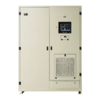
• TFA STS Dimensions: 60"W x 36"D x 84"H
• Clearances:
– Service clearance 36" front only
– Ventilation clearances:
○ 6" both sides and rear
○ 18" top
• Weight: Approx. 1800-2000 lbs. (Insure TFA STS floor loading does not exceed the raised floor loading
specifications. Obtain floor bracing if necessary.)
• If a floor stand is used, add floor stand weight (175-310 lbs. depending on height) to floor loading
computation: See table of floor stand weights in Figure 32, "TFA STS 800-1200A, Outline Drawing 4."
55..11..22 MMoouunnttiinngg TTFFAA SSTTSS oonn FFlloooorr
The TFA STS is front-access-only for installation as well as maintenance, service, and operation. In constrained
spaces, the Installer may not be able to reach the rear mounting holes of the side floor brackets. Consequently,
the TFA STS comes with (3) rear-mounted floor brackets that should be installed before moving the TFA STS
into place. The following placement procedure assumes that rear access is not available.
Placement procedure:
1. Determine the position of the TFA STS precisely, including clearances.
2. Install the (3) rear floor brackets based on your measurements and dimensions in the illustration below.

 Loading...