IB140042EN For more information visit: www.eaton.com
Instructional Booklet
Effective: May 2015 Page 25
ATC-300/900 Breaker Based Transfer Switch
4.7 Engine Start Connection
The engine control contact connections are located on the control-
lers of the ATS. It is always worthwhile to check the drawings in
order to connect the engine start contacts since there may have
been special wiring requested or the contacts may have been
wired to terminal blocks. The engine start terminals are marked 13
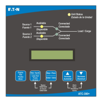
and 14 on J-5 connector on the ATC-300+ Controller (see Figure
24A). For the ATC-900 (Figure 24B) the contacts are on J15 4 &
5. See the individual controller instruction booklets for more
details. The IB s are: ATC-300+ Instruction Book (IB01602009E)
and ATC-900 Instruction Book (IB140012EN). A contact closes
between these terminal when an engine start signal is provided by
the Controller. The wiring diagram provides additional engine start
connection information. Use the proper wire size as listed by the
generator set (Genset) manufacturer.
Figure 24A. ATS Rear View of ATC-300+ Controller.
Figure 24B. ATS Rear View of ATC-900 Controller with DCT Mod-
ule Attached.
NOTICE
PRIOR TO MAKING THE ENGINE START CONNECTION TO THE
SWITCH, SET THE ENGINE GENERATOR CONTROLS SELECTOR
SWITCH IN THE OFF POSITION TO PREVENT AN UNWANTED
ENGINE START. IT IS RECOMMENDED THAT CONTROL WIRING,
SUCH AS THE ENGINE START WIRES, BE RUN IN A SEPARATE CON-
DUIT FROM THE POWER CABLES.

 Loading...
