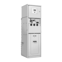
Do you have a question about the Eaton xiria series and is the answer not in the manual?
| Rated Voltage | Up to 24 kV |
|---|---|
| Rated Current | Up to 1250 A |
| Short Circuit Current | Up to 25 kA |
| Insulation Medium | Solid insulation |
| Application | Secondary distribution networks |
Explains the meaning of safety warnings used throughout the manual.
Outlines safety precautions for working on medium-voltage installations and personnel qualifications.
Specifies requirements for tools, aids, and protection equipment used with the unit.
Lists the relevant IEC and ISO standards applicable to the Xiria product.
Describes the information found on the unit's type plates, including specifications and serial numbers.
Provides an overview of the Xiria switchgear panels, their features, and applications up to 24kV.
Details cross-sections, single line diagrams, and lists functions for load-break and circuit-breaker panels.
Presents general technical specifications including weight, dimensions, and packing details for the Xiria unit.
Details transport, assembly, storage, and ambient conditions necessary for unit installation.
Outlines the steps involved in installing the Xiria unit, including lifting, travelling, and preparation.
Provides instructions and warnings for safely lifting the Xiria unit using designated equipment.
Explains how to move the unit on its pallet during transport to the assembly location.
Covers steps like removing packaging, checking contents, and preparing the installation site.
Describes rules for setting up the Xiria unit with an arc channel, including bore requirements.
Explains how to securely fix the Xiria unit to the floor using specified mounting patterns.
Details how to connect cables to the Xiria unit, including types and dimensions.
Lists the types of cables that can be connected and their maximum dimensions for cable compartments.
Provides instructions on strain relief, assembly, and securing cables to prevent mechanical forces.
Explains how to replace damaged cable connection cones and available types.
Details the procedure and safety precautions for applying test current and voltage to connected cables.
Describes how to connect the Xiria unit to the station earthing system using the earth bar.
Outlines the procedure for removing the front plate to access the secondary compartment.
Provides a summary and identification of the control units on the Xiria unit's control panels.
Explains how to perform manual switching operations, including operating position and cable earthing.
Details the procedures for switching the unit's operating position on and off, and to the neutral position.
Provides instructions for switching the cable earthing on and off, including checks and voltage detection.
Describes the procedure for gaining access to the cable when integrated earthing is ON, including safety rules.
Explains the built-in mechanical interlocks designed to prevent accidental switching operations.
Lists the types of built-in interlocks, including cable access, switch operation, and anti-reflex flap.
Details the earthed position interlock designed to prevent unintentional interruption of cable earthing.
Explains the interlock for the opening button to prevent unintentional switch opening.
Describes the interlock preventing unintentional closing of the switch and operation of the change-over switch.
Covers signals provided by the unit, including voltage detectors, overcurrent indicators, and trip indicators.
Explains the function and features of the voltage detectors conforming to IEC 61243-5.
Describes the overcurrent indicator that is activated by an overcurrent.
Details the trip indicator that shows if the switch was turned off by a protection relay.
Provides simplified instructions for switching between service and earthed positions.
Explains how the secondary space connects to the terminal strip for remote signalling and control.
Lists the unit positions that can be connected for remote signalling via auxiliary contacts.
Details remote control options, specifically 24 V DC remote tripping and closing.
Describes the components and commissioning for 24 V DC remote tripping.
Outlines components and commissioning for 24 V DC remote closing, including the closing motor.
Explains the 24 V DC tripping option for external protection on circuit-breakers.
Describes how to perform local closing operations using the electrical closing pushbutton.
States that the Xiria unit is theoretically maintenance-free, listing inspectable components.
Covers the procedures for inspecting cable connections, switching functions, and other components.
Provides a step-by-step guide for inspecting cable connections within the compartment.
Details how to inspect the switching functions, ensuring the unit is safe and operations are correct.
Explains how to check the moisture absorbing agent using a colour indicator.
Refers to Appendix 2 for inspection and maintenance of the voltage detection system.
Refers to the relay manufacturer's manual for inspection and maintenance.
Refers to Appendix 4 for inspection and maintenance of the overcurrent indicator.
Addresses decommissioning and environmental considerations for the unit.
Discusses environmentally friendly disposal and recycling of unit materials.
Lists the accessories supplied with the Xiria unit, such as operating handles and document holders.
Introduces the WEGA 1.2 integrated voltage detecting system and its compliance with standards.
Outlines the specifications for applying the WEGA 1.2 system, including user qualifications and network conditions.
Describes the physical design of the WEGA 1.2 system, including housing, display, and connections.
Presents technical specifications for the WEGA 1.2 system, including electrical and mechanical details.
Provides instructions on operating the WEGA 1.2 system, including functional controls and testing.
Gives guidance on storing, caring for, and transporting the WEGA 1.2 system.
States that the WEGA 1.2 system is maintenance-free, with notes on closing protective caps.
Explains that the WEGA 1.2 system's dot indication confirms continuous monitoring, making a maintenance test unnecessary.
Describes the ORION 3.0 unit for voltage, phase, and interface monitoring, including technical data.
Details the SIGMA type Short-Circuit Indicator for detecting short-circuits in medium-voltage networks.
Describes the Xiria system with tariff metering type MA, consisting of panels with circuit-breakers and transformers.
Specifies the design of a switchboard with tariff metering, detailing components in the right panel.
Explains the connection of primary main cables and voltage transformers using specific connectors.
Provides instructions on how to remove and remount current transformers for easier cable connection.
Describes the secondary front compartment and how to access it for metering connections.
 Loading...