4.4 Signals
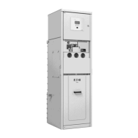
The Xiria unit features voltage detectors on the cable side
and can be fitted with overcurrent indicators and trip
indicators as options.
4.4.1 Voltage detectors
The Xiria unit features voltage detectors in the control
panel (12) conform IEC 61243-5 with LRM interface.
The voltage detector includes an LCD screen with
indication arrows and dots, one for each phase, see
Figure 4-17. These arrows and dots are present when the
cable is live.
The voltage detector detects wheather the operating
voltage is present at the cable connection of the panel
concerned.
The visible dot shows that the detector is
functioning correctly in accordance with the
demands for voltage detecting systems as
described in VDE 0682 art. 415.
This is a continuous internal function check.
In combination with the ORION 3 tester the voltage
detectors can also be used for phase comparison between
two adjacent live cables.
See appendix 4 for further information.
4.4.2 Overcurrent indicator
The overcurrent indicator (13), see Figure 4-18 is activated
by an overcurrent.
See Appendix 5 for further information.
4.4.3 Trip indicator
The trip indicator (10), see Figure 4-19, indicates whether
the switch has been switched off by the protection relay.
Resetting can be done by hand via the reset button on the
front.
Figure 4-17: Voltage detectors
Figure 4-18: Overcurrent indicator
Figure 4-19: Trip indicator

 Loading...