IM05805022K For more information visit: www.chfire.com
Instruction Booklet
Effective: January 2012 Page 3
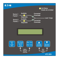
ATC-300+ Automatic
Transfer Switch Controller
Designed to meet the needs of markets worldwide, the
ATC-300+ Controller:
• Is a UL Recognized Component
• Complies with UL 1008/ CSA 22.2-178
• Meets the Intent of UL 991
• Meets IEC 1000-4-2, 1000-4-3, 1000-4-4, 1000-4-5,
1000-4-6, and 1000-4-11
• Meets CISPR 11, Class A
• Complies with FCC Part 15, Class A
• Meets European Standards Conformance (CE mark)
The ATC-300+ Controller provides an unmatched degree of pro-
grammed flexibility to address the needs of any system. It oper-
ates from all system voltages between 120 and 600 Vac, single-
phase and 3-phase, at 50 or 60 Hz. In addition, a period of no
control power operation is provided. The ATC-300+ Controller
monitors the condition of the 3-phase line-to-line voltage and fre-
quency of both the Source 1 and Source 2 power sources. It can
also be programmed for single-phase operation. The ATC-300+
Controller provides the necessary intelligence to insure that the
switch operates properly through a series of programmed sensing
and timing functions.
A standard ATC-300+ Controller will:
• Monitor Source 1 and Source 2 power source voltages and fre-
quencies;
• Provide undervoltage monitoring of the Source 1 and Source 2
power sources;
• Permit customer programming;
• Display real-time and historical information;
• Permit system testing;
• Store customer/factory established parameters in nonvolatile
memory; and
• Provide faceplate source status indications.
1.4 Glossary
With respect to their use within this document and as they relate
to ATS and controller operation, the following terminology is
defined.
Available
A source is defined as “available” when it is within its undervolt-
age/overvoltage/ underfrequency/overfrequency setpoint ranges
for the nominal voltage and frequency setting.
Connected
Connected is defined as when the input is shorted by an external
contact or connection.
Failed or Fails
A source is defined as “failed” when it is outside of the applicable
voltage and frequency setpoint ranges for the nominal voltage and
frequency setting for a time exceeding 0.5 seconds after the time
delay emergency fail (TDEF) time delays expires.
Failsafe
Failsafe is a feature that prevents disconnection from the only
available power source and also forces a transfer or re-transfer
operation to the only available power source.
Re-Transfer
Re-transfer is defined as a change of the load connection from the
Source 2 to the Source 1.
Source 1
Source 1 is the primary source (normal source, normal power
source, or normal).
Source 2
Source 2 is the secondary source (emergency source, emergency
power source, emergency, standby, or backup source).
Source 1: Failed or Fails
Source 1 is defined as “failed” when it is outside of its undervolt-
age/overvoltage/ underfrequency/overfrequency (if applicable) set-
point ranges for the nominal voltage and frequency setting.
Source 2: Failed or Fails
Source 2 is defined as “failed” when it is outside of its undervolt-
age/overvoltage/ underfrequency/overfrequency (if applicable) set-
point ranges for the nominal voltage and frequency setting for a
time exceeding 0.5 seconds after the TDEF time delay expires.
Transfer
Transfer is defined as a change of the load connection from the
Source 1 to the Source 2 power source, except when specifically
used as “Transfer to Neutral”.
Transfer to Neutral
Transfer to neutral is defined as when the load circuits are discon-
nect from both the Source 1 and Source 2 power sources.
Unconnected
Unconnected is defined as when the input is not shorted by an
external contact or connection.
V
IN, RMS
Refers to the operating input voltage (Vac, RMS).
1.5 Functions/Features/Options
The primary function of ATC-300+ Controller is to accurately
monitor power sources and provide the necessary intelligence to
operate an ATS in an appropriate and timely manner. In addition,
the ATC-300+ Controller provides programming through the
device’s faceplate or communication option.
1.5.1 Operational Simplicity
From installation to programming to usage, the ATC-300+ Con-
troller was designed with operational simplicity in mind. Only one
style needs to be considered, regardless of input/output require-
ments or system voltages and frequencies. The ATC-300+
Controller provides the functionality of numerous other devices
combined in one package that mounts in 6.5 by 8.5 inches of
panel space.
The user-friendly front panel interface simplifies routine operation,
programming, data presentation, and setting adjustments. An
LCD-based display provides the flexibility of a back-lit display for
enhanced visibility. The operation of the front panel membrane
pushbuttons move the ATC-300+ Controller display from function
to function or step to step within a function.

 Loading...


