IM05805022K For more information visit: www.chfire.com
Instruction Booklet
Effective: January 2012 Page 7
ATC-300+ Automatic
Transfer Switch Controller
Section 2: Hardware Description
2.1 General
The purpose of this section is to familiarize the reader with the
ATC-300+ Controller hardware, its nomenclature, and to list the
unit’s specifications. The information presented is divided into
the following three parts:
• Operator Panel;
• Rear Access Area; and
• Specification Summary.
2.2 Front (Operator) Panel
The front panel, depending on the installation, is normally acces-
sible from the outside of a panel or door. The front panel provides
a means to:
• Alert the user to specific conditions;
• Program the controller; and
• Set and monitor the operating parameters.
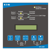
The ATC-300+ Controller front panel serves two primary func-
tions: output and input. The output function consists of:
• A two-line, 16 character LCD display module
• Five LED outputs
1 Unit Status
2 Source 1 Available
3 Source 1 Connected
4 Source 2 Available
5 Source 2 Connected
There are seven input functions accessible through the pushbut-
tons:
1 Help/Lamp Test
2 Engine Test
3 Step/Enter
4 Increase
5 Decrease
6 Alarm Reset
7 Bypass Time Delay
Figure 1. The ATC-300+ Controller Front Panel.
2.2.1 The Output Function Components
The Display
A 2-line, 16-character alphanumeric LCD Display module is used
to display all ATC-300+ Controller monitored parameters, set-
points, and messages in easy to read formats. The display has a
green high contrast background that allows clear visibility of any
information displayed. The display is continuously lit for clear vis-
ibility under poorly lit or no light conditions.
Six different displays can be presented via the LCD Display:
• Status Display
• Source 1 Display
• Source 2 Display
• Time/Date Display
• History Display
• Setpoints Display
As a default when there are no active commands or timers being
displayed, the display shows information from the source that is
connected to the load. This is referred to as the “Home” screen.
Line 1: Source 1 or 2 Metered Voltage
Line 2: Date Time
Example: Source 1 480V
1/20/06 3:35PM
See Section 3 for more detailed information.

 Loading...


