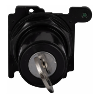
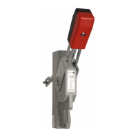
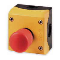
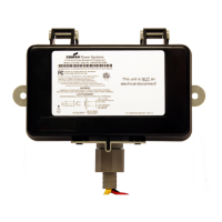
CCP2-H4X-_ pistol handles for 12 mm shafts
Installation manual 3A3718 Rev E
Effective February 2019
Eaton and Bussmann are valuable trademarks
of Eaton in the U.S. and other countries. You
are not permitted to use the Eaton trademarks
without prior written consent of Eaton.
ANSI is a registered trademark of the
American National Standards Association
IEEE is a registered trademark of the Institute
of Electrical and Electronics Engineers
NEMA
is a registered trademark of the
National Electrical Mfgrs. Association
NFPA
is a registered trademark of the National
Fire Protection Association
UL
is a registered trademark of the
Underwriters Laboratories, Inc.
Eaton
1000 Eaton Boulevard
Cleveland, OH 44122
Eaton.com
Bussmann Division
114 Old State Road
Ellisville, MO 63021
United States
Eaton.com/bussmannseries
© 2019 Eaton
All Rights Reserved
Printed in USA
Publication No. 3A3718
January 2019
12
Step 8: Check the distance the shaft coupler extends beyond the
enclosure’s side as shown. If extension is to too great, recut shaft
accordingly and reinstall. If too short, install another shaft per
previous instructions.
Step 9: Prepare the handle backer plate for mounting by removing
the depth gauge as shown.
Step 10: Place switch handle on the enclosure’s side so that the
protruding screw guides are seated in the four mounting holes. From
the inside, place the backer plate in position and secure with four
supplied Phillips head screws. Torque to 1 N•m (8.9 lb-in) as shown.
Step 11: Check switch for proper operation in all modes. If not
operating correctly, revisit these installation steps for remedial
action.
NOTE: Side installation (handle mounted on the enclosure’s side and
not the door) does NOT provide for an interlock means to prevent
opening the door while the switch is in either the ON or OFF
position. If preventing access to the enclosure’s interior is desired
or required by the application, use a locking door latch or install a
suitable hasp to accept a lock.
Step 7: Fully insert the shaft back into the switch making sure its
indexing corner (largest flat on the shaft) is in the upper left corner
of the switch shaft hole. Torque setscrew to 2.5 N•m (22 lb-in) using
4 mm Allen wrench. Place shaft coupler on the shaft as shown and
torque setscrew to 2.5 N•m (22 lb-in) using 4 mm Allen wrench.
Note the shaft is indexed so the shaft coupler can only be inserted
one way.
23 mm (0.91”)
8
7
Z 2/#2
1 N•m (8.9 lb-in)
10
11
9
OFF
ON
OFF
4 mm
2.5 N•m
(22 lb-in)
 Loading...
