I.L. 17562
Page 67
PR 0.3 Effective 8/99
SECTION 6. INSTALLATION AND WIRING
6.1 Mounting — The following subparagraphs describe the mounting of the MP-3000 relay, as
well as its optional URTD module and PONI Communications module.
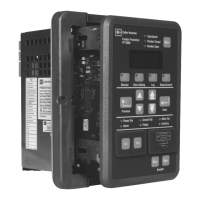
6.1.1 Mounting the MP-3000 — Mount the unit vertically on a flat panel. The location should
be as free as possible of water, chemicals, dust, and excessive heat and vibration. The panel
should protect the user from accidental contact with live terminals on the back of the MP-3000.
A 1/8 inch steel panel or door, solidly grounded, is recommended.
Before actually cutting the panel, check the required three-dimensional clearances for the MP-
3000 case, particularly behind the panel. See dimensions in Figures 6.2 and 6.3. If mounting on
a swinging door, check the swinging clearance of rear projections and wired connections.
Figure 6.1 shows dimensions for the panel cutout and mounting holes. Cutout tolerances and
mounting screw hole placement are critical. In particular, the tolerance of the horizontal
dimension between the center of the mounting holes and the vertical edge of the cutout must be
between 0 and +0.050 in. (0.13 cm).
NOTE
The cutout is the same as for the previous-generation IQ 1000 II motor relay, and other Cutler-
Hammer IQ products of this case size. The six mounting holes which secure these older
products are still correctly located for the MP-3000, but the four additional new holes should be
added.
Secure the MP-3000 to the panel with the special self-tapping plastic screws. Use moderate
torque - 8 inch pounds. Use the 0.375-inch-long (0.75 cm) screws supplied with the relay to
mount the unit on a 1/8 inch panel. Do not attempt to tap the holes. Do not use machine
screws.
6.1.2 Mounting the URTD Module — The optional URTD module provides temperature data to
the MP-3000 from up to 11 RTDs embedded in the motor and driven equipment. See URTD I.L.
17367.
The URTD module may be mounted either on the back of the MP-3000 by using the URTD
mounting bracket and machine screws (supplied with the URTD module), or mounted remotely
from the MP-3000. If mounting the URTD module on the back of the MP-3000, see Figure 6.3
for overall depth dimensions. See Figure 6.4 for URTD stand-alone mounting dimensions.
Consider the benefit of mounting the URTD module away from the MP-3000, as close as
possible to the motor. The big bundle of RTD wires becomes much shorter. The URTD conveys
multiplexed temperature data back to the relay via a single optical fiber (recommended) or by a
3-wire communications conductor. The URTD may be placed up to 400 feet from the MP-3000
with the optical fiber connection (recommended), or up to 500 feet away with a wired
communications connection. Note that the URTD will require 120 Vac power (6 VA) at its remote
location. It may be mounted in any orientation.
6.1.3 Mounting the PONI Communications Module — See Section 10 for a description of the
various types of optional PONI communications modules which can be used with the MP-3000.
Check the I.L. for the selected PONI to confirm dimensions and communications network
connection requirements.
Figure 6.3 shows clearance dimensions to the rear for an I-PONI, B-PONI, or D-PONI. An RS-
232 PONI is 0.1 inch deeper. An E-PONI is 0.5 inch deeper.

 Loading...


