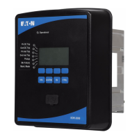
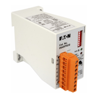
DT3000 Instruction Leaflet
I.B. 17555D Effective: Date 07/02 Page 33
For more information visit: www.cutler-hammer.eaton.com
Supersedes I.B. 17555C dated November 1999
DT3000 Protective Relay
Power Supply Input.
TB1-6/TB1-5
AC 120-240 Vac, 50/60 Hz
DC 48-250 Vdc
Caution - Refer to
.
Instruction Leaflet
Open
2
Program with B reaker Open/Closed
4
6
7
5
3
9
10
8
Breaker Input Mode
Reserved
Download Setpoints
Reset
Zone I nterl ocking
Close Relay Config.
Remote open/close
Relay Configuration
Disable
Unlatched
Comm. Close
OC/INST
Manual
Disable
Auto
52a
Enable
52b
Phase/Gnd.
Hi Load Alm.
Enable
Latched
1
FUNCTION
IMPACC Buffers
OFFON
DT3000 DTMV
Fig. 5-2 Digitrip 3000 Protective Dimensions (Inches)
TABLE 5.1 DIGITRIP 3000 DIP SWITCH SETTINGS
SWITCH POSITIONS
Switch FUNCTION
ON (=0) OFF (=1)
S1 PowerNet/IMPA
CC Buffers
Digitrip 3000 Digitrip
MV
S2 Program with
Breaker
Open or
Closed
Open Only
S3 Trip Relay
Configuration
Phase /
Ground
OC/Inst
S4 Remote
Open/Close
Enable Disable
S5 Close Relay
Configuration
Hi Load
Alarm
Comm.
Close
S6 Zone Interlocking Latched Unlatched
S7 Breaker Input
Mode
52a 52b
S8 Download Set
points
Enable Disable
S9 Reset Auto Manual
S10 Reserved XXXX XXXX
For additional DIP Switch information, refer to
Paragraph 2-2.2
5-4 WIRING
The wiring of the Digitrip 3000 Protective Relay must follow
a suitable “wiring plan drawing.” The term wiring plan, as
used here, refers to the drawings made for the specific
application. It describes all electrical connections between
the Digitrip 3000 and external equipment. The user makes
this drawing. It may also be helpful to refer to the relay’s
specific wiring diagram shown in Figure 3-1. An example of
a typical wiring plan is shown in Figure 2-1. Note the
following:
1. The wires to the terminal blocks must not be larger
than AWG No. 14. Larger wire will not connect
properly to the terminal block. However, larger size
wires can be used for the Ct connections, with
appropriate ring terminal.
2. The terminal block has No. 6-32 sems pressure
saddle screws.
3. All contacts are shown in their de-energized position.
Note that the Protection Off Alarm Relay is energized
when control power is applied.
4. The Digitrip 3000 comes with zone interlocking
jumpers installed (TB1 Terminals 11 to 12 and 13 to
14). Depending on the application of zone interlocking,
these jumpers may have to be removed.
Note: Refer to the Specifications and Test Summary
for proper power supply input requirements. All wiring
must conform to applicable federal, state and local codes.
5-5 INITIAL STARTUP
Use this information when first applying control power to
the Digitrip 3000 Protective Relay.

 Loading...


