EasyManuals Logo

Eaton Durant Eclipse Series User Manual

Eaton Durant Eclipse Series
53 pages
To Next Page IconTo Next Page
To Previous Page IconTo Previous Page
Page #15 background imageLoading...
Page #15 background image
14
WIRING cont.
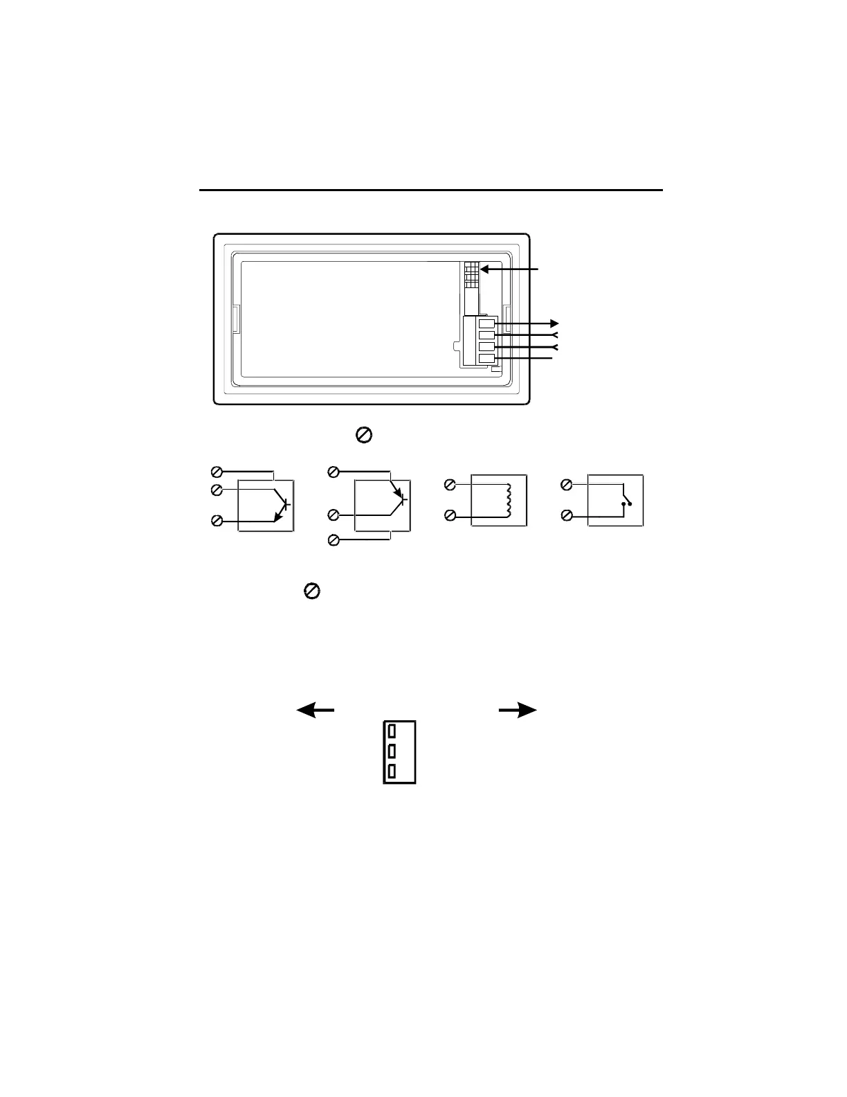
Flowmeter Input Wiring and DIP Switches
DIP Switch Position 3
1
3
2
4
Durant
®
X
+12 VDC Out
Flowmeter Input
Inhibit Input
Ground
Typical Flowmeter wiring (3 denotes terminal number)
4
3
1
DIP 1 ON
+
NPN
OUT
COMMON
4
3
1
DIP 1 OFF
+
PNP
OUT
COMMON
3
1
DIP 3 ON
2 Wire MAG Pickup
3
1
DIP 2 ON
Contact (Reed Switch, etc.)
The inhibit input (2 ) is wired the same way, and DIP switches 1, 2, and 3 are set
accordingly.
Sensor Power Out
12 VDC, 75 mA max, short circuit protected
Dip Switch Settings
OFF ON#
Single Ended
Fast Response (>50 Hz)
Sourcing (PNP) Input
3
2
1
Mag Pickup
Slow Response (<50 Hz)
Sinking (NPN) Input

Other manuals for Eaton Durant Eclipse Series

Questions and Answers:

Question and Answer IconNeed help?

Do you have a question about the Eaton Durant Eclipse Series and is the answer not in the manual?

Eaton Durant Eclipse Series Specifications

General IconGeneral
BrandEaton
ModelDurant Eclipse Series
CategoryMeasuring Instruments
LanguageEnglish

Related product manuals