Effective May 2019
Supersedes February 2015
PXBCM-MB-BASIC
PXBCM-MB-ENERGY
Instruction Leaflet IL150001EN
Power Xpert Branch Circuit Monitor:
Meter Base - Basic and Energy Code Series
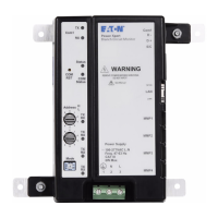
COM reset
button
Base mounting
screws #8
LED Indicators
Configuration
switches
Com1/2 RS485
Modbus RTU
LAN Ethernet
RJ45 CAT5+
STP
MMP 1-4 Meter
Module ports
Power Supply Mains Terminal PE/N/L
Base mounting
screws #8
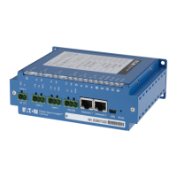
Figure 1. PXBCM-MB controls, connectors and indicators.
The PXBCM-MB is the data acquisition module/
gateway of the PXBCM system. The PXBCM-
MB aggregates the meter data from up to four
PXBCM-MMS and PXBCM-MME meter modules.
You can access the data from all channels (includ-
ing virtual meters) through the RS485 COM1 or
COM2 Modbus port using the RS-485 RTU proto-
col, or the LAN Modbus TCP connection, or view it
directly through the onboard web server.
The Modbus address is set through a pair of
rotary switches (Address H-L) on the front of the
PXBCM-MB housing. Indicator lights show device
status (Status) as well as communications sta-
tus for both LAN Ethernet and COM1 or COM2
Modbus. A mode switch determines user access
security levels.
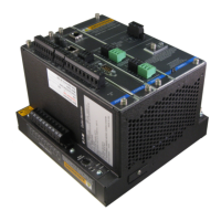
The PXBCM-MB must be housed in an appropriate
NEMA or UL enclosure that ensures the device
will remain within its specified environmental
ranges and provides fire and mechanical protec-
tion. In retrofit panel board applications the MB
must be mounted in an enclosure external from
the monitored assembly gear, unless the MB is an
approved accessory for the panel board.
Each Meter Module has the following LED
Indicators
•
COM1 or COM2 Rx/Tx Green/Red LEDs –
RS485 Modbus
•
MMP 1-4 Rx/Tx Green/Red LED – Meter
Module Port communications
•
LAN Ethernet LEDs in RJ45 jack
• Link Green on = Link Active, blink for TxRx
• 10/100 Speed - Amber off/on
•
Status Green/Red bicolor LED –
• Green ~ 1Hz blink – Normal heart beat
• Red – Application alarm
•
Com Status: Green/Red bicolor LED:
• Green on = DHCP, Green off = Fixed IP
• Red on = communications reset mode
PXBCM-MB Meter Base
Specifications
•
Weight ~ 1 lb
•
W/H/D: 7.0”(17.6 cm)/6.3”(15.8cm)/2.6”(6.6cm)
•
Each Meter Base can interface to 1-4 Meter
Modules (-MMS &/or –MME)
•
Housing NEMA 1, IP20
•
Pollution Degree 2
•
Operational Temperature range -20 to +70ºC
•
Storage Temperature range -45 to +85ºC
•
Elevation 0-3000m
•WARNING!
BE SURE THAT ALL SYSTEM POWER IS OFF WHEN COMMISSION-
ING A PXBCM SYSTEM INCLUDING THE INSTALLATION OF THE
PXBCM-MB METER BASE AND ASSOCIATED COMPONENTS.
Overview
For use with the Power Xpert Branch Circuit Monitor (PXBCM) Basic and
Energy Code Series meter bases (MB) -
Both the PXBCM-MB-BASIC meter
base and PXBCM-MB-ENERGY meter base are designed to be used with
the PXBCM–MME Meter Module External and/or – MMS Meter Module
Strip. The Meter Base (MB) sources power to and collects data from the
Meter Modules through the Meter Module Ports and Cables.
•
PXBCM-MMS-(L/R 9/15/21)-A Meter Module Strip
•
PXBCM-MME-X25-333MV Meter Module for External CTs
•
PXBCM-MME-X21-100MA Meter Module for External CTs
•
PXBCM-MMP-CBLnn/-CBLEnn Meter Module Port Cable and Cable
Extension