Do you have a question about the Eaton Moeller Series and is the answer not in the manual?
Explains CMD use in safety-related circuits for emergency shutdown via contactors.
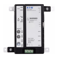
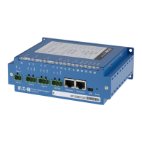
Details the CMD device, power supply requirements, and compatible Eaton components.
Specifies incorrect combinations and configurations to avoid for the CMD device.
Clarifies CMD approval under EN/ISO 13849 and setup per IEC/EN 60204-1.
Details CMD support for control systems meeting Performance Level "d" as per EN/ISO 13849-1.
Explains CMD use in Category 3 systems with DOL or reversing starters.
Covers DCavg calculation for parallel channels involving CMD and its components.
Provides formulas and values for MTTFd calculation for CMD and related parts.
Lists IFA approval, CE declaration, UL/CSA approval, and product standards.
States that no specific EMC measures are required for the CMD device.
Describes mounting the CMD device on a top-hat rail in any position.
Covers connection for DOL/reversing starters and insulation voltage requirements.
Details permissible cable cross-sections and tools for wiring CMD relay terminals.
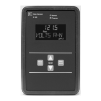
Explains the function of the two internal LEDs (Contr. and UVR) for status indication.
Describes the requirement for regular testing of the undervoltage release via the Test button.
Shows nameplate details including voltage, certifications, and standards.
Lists general technical data like lifespan, operating frequency, temperature, and weight.
Provides physical dimensions and clearance requirements for the CMD device.
| Brand | Eaton |
|---|---|
| Model | Moeller Series |
| Category | Measuring Instruments |
| Language | English |