18
(totalizer, totalizer with relays, or batcher) and the functions necessary for the particu-
lar application (reset, unlatch, start, etc.), determine the function(s) of each control
input and select an input device appropriate to the function.
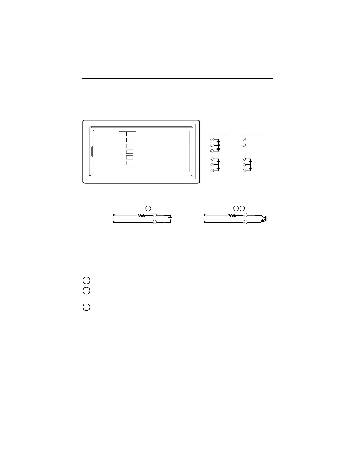
Relay Output
Durant
®
Terminal Designations
Output
2
Output
1
6
5
4
3
2
1
6
5
4
3
2
1
Output
2
6
5
Output
1
3
2
1
+
-
Dual Relay Relay/Transistor
Typical Wiring
Load
1
External
AC or DC
Power
+
-
Load
2
Relay
3
6
Transistor
5
External
DC
Power
Relay Contact Ratings
5 A @250 VAC or 30 VDC maximum
Transistor Ratings
OFF state: Block 30 VDC max, 0.1 mA max leakage current
ON state: Conduct 50 mA max, 1.2 V max C-E voltage drop
1
An RC surge suppressor is recommended across all inductive loads.
2
The transistor is optically isolated and may be connected as a sink (shown), or
a source by wiring the load between terminal 5 and - (minus).
3
A reverse-biased diode (1N 4001 or equiv.) is recommended across all
inductive loads.
General Wiring Practices
Use shielded cables for signal and control inputs.
Keep all signal lines as short as possible (<30M or 100 ft.).
Do NOT bundle or route signal lines with power or machine control wiring.
Do not allow signal or control wires to leave the building.
WIRING cont.