7
Instruction Booklet IB0162064EN
Effective January 2014
O & M Manual for the EGS Service
Entrance Automatic Transfer Switch
Eaton Corporation www.eatoncanada.ca
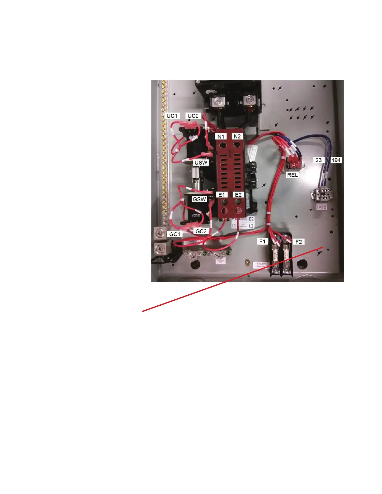
UC1: Utility Coil 1
UC2: Utility Coil 2
N1: Normal (utility ) 1
N2: Normal (utility) 2
USW: Utlity switch position
GSW: Generator switch position
GC1: Generator coil 1
GC2: Generator coil 2
E1: Emergency line 1
E2: Emergency line 2
L1: Load line 1
L2: Load line 2
F1: Fuse line 1 (used for utility sensing to generator)
F2: Fuse line 2 (used for utility sensing to generator)
REL: Transfer signal Relay
23, 194: Transfer signal connection from generator
Install T1 Fuse Block (provided with gen-
erator) in this position, install jumper to L1
or L2 to ensure generator battery is charging
when on utility and on generator source
Figure 5. Typical Basic 100 Ampere Interior
Assembly.
 Loading...