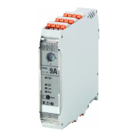
3 Plug-in motor starter ROSF for mounting on an adapter
3.2 Layout of devices with adapter EMS2-XTH
22 EMS2… Electronic motor starter 10/19 MN034003EN www.eaton.com
Figure 11:Mounting on adapters
3.2 Layout of devices with adapter EMS2-XTH
When using EMS2-ROSF devices with a rated operational current I
e
of 9 A in
(AC51) conjunction with the adapter EMS2-XTH, note that the permissible
thermal continuous current depends on the type of mounting and the ambi-
ent temperature. See diagram below.
Moreover, the maximum permissible current must not be exceeded, even in
startup.
Figure 12: Thermal continuous current I
L
depending on the ambient temperature
a When mounting the devices with a minimum distance of 20 mm
b For directly linked devices
The maximum current during start-up of the motor is derived by multiplying
the motor rated current with the “startup factor”, which with standard asyn-
chronous motors is usually between 6 and 10.
Contact the motor manufacturer to establish the actual value.
MSFS
EMS2-XTH
T
A
[°C]
EMS2-XBB-60
T
S
[°C]
→
It is not permitted to use the motor starters described in this
Section in potentially explosive areas (ATEX).
Only motors in potentially explosive areas may be controlled.
T
A
[°C]
0 102030405060
6
8
0
4
2
9
7
5
3
1
I
L
[A]
①
I
e
= 3 A
I
e
= 9 A
①
②
②
 Loading...