6 Status messages
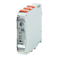
6.1 LEDs on the front of the device
EMS2… Electronic motor starter 10/19 MN034003EN www.eaton.com 41
Table 11: Status messages – combination of four LEDs
LED Status Description Reset
PWR ERR L / (–) R / (ON)
Off No control voltage U
S
present –
Ready for operation Control voltage U
S
present –
Drive switched on Counterclockwise operation (L) –
Drive switched on Clockwise operation (R or ON) –
Internal error Device needs to be replaced Not possible
Motor protection tripped during
counterclockwise operation
→ section 4.2, “Motor protec-
tion”, page 27
Motor protection in cooling-down
phase,
reset not possible.
Manually after a cooling-down time
of approx. 2 min;
automatically after approx. 20 min
with a bridge between AUT and RES
Motor protection tripped during
counterclockwise operation
→ section 4.2, “Motor protec-
tion”, page 27
Cooling-down phase concluded,
manual reset possible
Manually after a cooling-down time
of approx. 2 min;
automatically after approx. 20 min
with a bridge between AUT and RES
Motor protection tripped during
clockwise operation
→ section 4.2, “Motor protec-
tion”, page 27
Motor protection in cooling-down
phase,
Reset not possible.
Manually after a cooling-down time
of approx. 2 min;
automatically after approx. 20 min
with a bridge between AUT and RES
Motor protection tripped during
clockwise operation
→ section 4.2, “Motor protec-
tion”, page 27
Cooling-down phase concluded,
manual reset possible
Manually after a cooling-down time
of approx. 2 min;
automatically after approx. 20 min
with a bridge between AUT and RES
Bad checksum Error during system recovery. The ther-
mal memory of the motor protection
function is set to the maximum value.
The error must be manually acknowl-
edged in automatic mode.
Manual
Asymmetrical phase current The currents in the phases deviate
from one another by more than 33%.
Manual
Motor is stalled
(counterclockwise operation)
The maximum measurable motor
current is exceeded for longer than 2 s.
Manual
Motor is stalled
(clockwise operation)
The maximum measurable motor
current is exceeded for longer than 2 s.
Manual
•Phase failure
• No motor connected
• Motor current < I
min
for longer
than 2 s
Error has occurred during counter-
clockwise operation. The power circuit
is still connected.
Automatic, as soon as the error has
been remedied
•Phase failure
• No motor connected
• Motor current < I
min
for more
than 2 s
Error has occurred during clockwise
operation. The power circuit is still
connected.
Automatic, as soon as the error has
been remedied
 Loading...