4
Technical Data TD00801003E
Effective November 2011
Elevator Control ES Switch
EATON CORPORATION www.eaton.com
Other Options
Optional features include contact closure, i.e. battery lowering/
door opening system. The B option offers support for the states of
Arizona, Oregon, and Texas requirements to prevent “nuisance” fire
alarms by over-riding the “Control Power not Available” signal when
the Eaton Elevator Control ES disconnect is manually (intentionally)
turned off, and distinctive signaling for ON-OFF-TRIPPED conditions
(Option B).
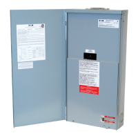
All Eaton Elevator Control elevator disconnect switches are UL-Listed
and designed for safe access by qualified personnel. When main-
tenance or shutdown service is required, no energized parts are
exposed inside the enclosure when the disconnect switch is manual-
ly turned to the OFF position. For proper maintenance safety precau-
tions, always turn off incoming power to the Eaton Elevator Control
ES elevator switch when possible. When servicing any live electrical
equipment, always wear appropriate personal protective equipment.
DANGER
ELECTRICAL SHOCK HAZARD. ELECTRICAL EQUIPMENT MAY CONTAIN
HAZARDOUS VOLTAGES. THESE CAN CAUSE ELECTRICAL SHOCK, BURN
OR DEATH. ONLY QUALIFIED PERSONNEL SHOULD PERFORM PROCEDURES
INVOLVING ELECTRICAL EQUIPMENT. ALWAYS PROPERLY GROUND EQUIP-
MENT AND LOCKOUT ELECTRIC POWER (DE-ENERGIZE) BEFORE ACCESS-
ING ELECTRICAL EQUIPMENT AND ENCLOSURES. ALL DEADFRONTS AND
OTHER SHIELDING MUST BE IN PLACE BEFORE ENERGIZING THIS DISCON-
NECT SWITCH. TAKE NOTE OF AND FOLLOW ALL SAFETY INSTRUCTIONS
IN THIS INSTRUCTION LEAFLET.
Shunt-Trip Operation
The disconnecting means is a shunt-trip operated switch. The control
power source for the shunt-trip operator is a 120 Vac supply originat-
ing in the Eaton Elevator Control ES switch. Current to the shunt-trip
device is switched by an isolation relay, which is in turn controlled by
the FACP.
The control signal may be either 24 Vdc from the FACP (Option R2)
or a “dry” contact closure in the FACP (Option R1). In the case of a
“dry” contact closure, the sensing voltage is 120 Vac originating in
the Eaton Elevator Control ES switch.
A key test switch (Option K) is included for testing the shunt-trip
circuit.
Supervisory Indication
Additionally, an optional separate relay can be specified to monitor
the 120 Vac control power source in the Eaton Elevator Control ES
switch. This relay (Option F1 or F3) is used to provide supervisory
indication of “Control Power Available” as required by NFPA 72
Section 6.15.4.4.
Table 1. Transformer Fuse Table.
ECS Voltage/
Transformer Voltage
Primary
Fuse (amps)
Secondary
Fuse (amps)
208/120 FNQ-R-2 FNM-1 1/4
240/120 FNQ-R-2 FNM-1 1/4
480/120 FNQ-R-1 FNM-1 1/4
600/120 FNQ-R-1 FNM-1 1/4
Table 2. Lug Torque Specifications.
Molded Case Switch Fuse Base Neutral Mains
Catalog Ampacity Main Lugs (Line)
Number Wire Size Range Torque Wire Size Range Torque Wire Size Range Torque
Prefix Wire Size in lb Wire Size in lb Wire Size in lb
ES1 30 Amp 14 - 1/0
14 - 10 AWG 35
2 - 14 AWG
14 - 10 AWG 35
2 - 14 AWG
14 - 10 AWG 35
8 AWG 40 8 AWG 40 8 AWG 40
6 - 4 AWG 45 6 AWG 45 6-2 AWG 45
3 - 4/0 50
ES2 60 Amp 14 - 1/0
14 - 10 AWG 35
2 - 14 AWG
14 - 10 AWG 35
2 - 14 AWG
14 - 10 AWG 35
8 AWG 40 8 AWG 40 8 AWG 40
6 - 4 AWG 45 6 AWG 45 6 -2 AWG 45
3 - 4/0 50
ES3 100 Amp 14 - 1/0 14 - 1/0 50 14 - 1/0 14 - 1/0 50 14 - 1/0 14 - 1/0 50
ES4 200 Amp
4 - 4/0
(3/16 hex recess)
4 - 4/0 120
4 - 300 kcmil
(5/16 hex recess)
4 - 300 kcmil 275 6 - 250 kcmil 6 - 250 kcmil 275
ES5 400 Amp (2) 2 - 500 kcmil (2) 2 - 500 kcmil 375
(2) 1/0 - 300 kcmil
or
(1) 750 kcmil
(2) 1/0 - 300 kcmil
or
(1) 750 kcmil
500
(2) 1/0 - 300 kcmil
or
(1) 750 kcmil
(2) 1/0 - 300 kcmil
or
(1) 750 kcmil
500

 Loading...